Adjustment method of dot printing positions and a printing apparatus

a technology of printing apparatus and adjustment method, which is applied in the direction of printing mechanism, spacing mechanism, printing, etc., can solve the problems of reducing image quality, difficult to realize, and increasing the cost of printing apparatus, and achieves excellent operational performance, low cost, and low cost

Inactive Publication Date: 2002-09-24
CANON KK
View PDF27 Cites 57 Cited by
  • Summary
  • Abstract
  • Description
  • Claims
  • Application Information

AI Technical Summary

Benefits of technology

Namely, it has been desired strongly that the apparatus or system capable of printing the image at a high speed and of the high-quality image without occurring the problem on the image formation as above-mentioned and the problem on the operability is realized at a low cost by designing to be able to register the depositing position without using a feedback controlling means such as an encoder by an opened loop.
Therefore, the object of the invention is to realize a dot alignment method which is excellent in operational performance and the low cost.
Moreover, the invention, without fundamentally enforcing the user the judgment and the adjustment, is designed to detect the optical characteristics of the printed image to derive the adjustment condition of the optimum dot alignment from the detected results and to set the adjustment condition automatically, thereby to improve the adjustment accuracy thereof.

Problems solved by technology

However, it has been thought that since to form such a feedback controlled system causes an increase in the cost of the printing apparatus, it is difficult to realize this, in the printing apparatus which is relatively cheap.
For example, in the case of the ink-jet print head, the slight differences, which is generated in a print head manufacturing step, such as variations of a form of ink ejection openings and the elements for generating energy for ejecting ink such as an electro-thermal converting elements (ejection heaters), influence a direction and an amount of ejected ink, and result in the cause which makes the unevenness in density of the image which is formed finally to reduce the image quality.
Due to bi-directional printing, the following problems has been caused.
When the multi scanning printing is used along with bi-directional printing in order to improve in high image quality, even though in bi-directional printing the depositing positions are not registered, as an effect of the multi scanning printing the offset in the pixel level is not easy to be seen, but from a macroscopic viewpoint the entire image can be seen unequally and is recognized as an unpleasant figure by the user.
(Problems in the Case of Performing the Image Formation Using a Plurality of the Print Heads)
Moreover, though this deviation in color matching does not become easy to be seen in the case of an ordinary paper, it becomes easy to be seen, when a favorable printing medium in color development such as a coat paper is used.
However, the complicatedness that the user should observe the results which the depositing registration conditions are varied by the eyes to select the optimized the depositing registration condition to perform entering operations is accompanied, and moreover, since fundamentally, a judgment for obtaining the optimum printing position by observing through eyes is enforced on the user, the establishment which is not optimized can be set.
Therefore, it is especially unfavorable to the user who is not accustomed to operation.
Moreover, the user is enforced to expense in time and effort at least two times since the user should printing the image to perform the depositing registration and in addition, to perform conditional establishment after observing to perform judgments required, whereby upon realizing the apparatus or a system excellent in operability, it is not only desirable but also is disadvantageous from the viewpoint of a time-consumption.

Method used


Image

  • Adjustment method of dot printing positions and a printing apparatus
  • Adjustment method of dot printing positions and a printing apparatus
  • Adjustment method of dot printing positions and a printing apparatus

Examples


second embodiment

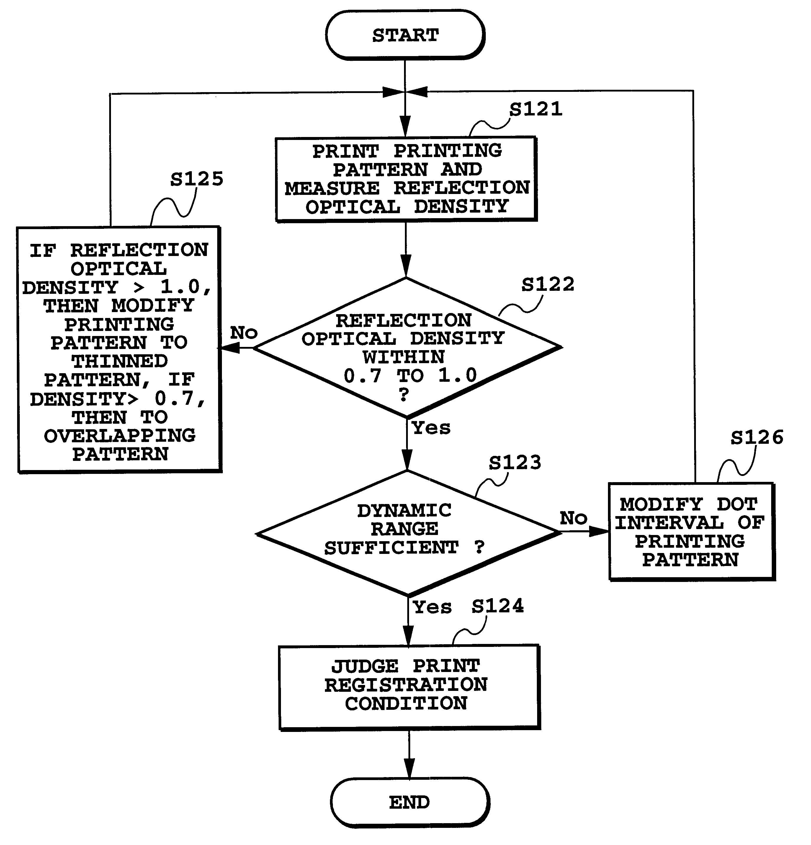
FIG. 24 is a flowchart illustrating printing registration processing in the This processing can be applied as a part of processing in general algorithm described later.

As shown in FIG. 24, at step S121, the nine patterns 61-69 shown in FIG. 17 are printed as the printing patterns. The reflection optical density of the printing pattern is measured in the same manner as in the bi-directional printing.

Next, at step S122, a decision is made as to whether or not the highest one among the measured reflection optical densities falls within a range of 0.7 to 1.0 of an OD value. If the value falls within the predetermined range, the operation proceeds to a next step S123.

If the result at step S122 is that the reflection optical density does not fall within the range of 0.7 to 1.0, the operation proceeds to step S125. At step S125, the printing pattern is modified to patterns shown in FIGS. 23A to 23C where the dots of the printing pattern are thinned to two thirds when the value is greater ...

first embodiment

In FIGS. 25A to 25C, white dots 72 represent dots printed by the first printing head, and hatched dots 74 represent dots printed by the second printing head. FIG. 25A illustrates dots in the case where the printing positions are well registered; FIG. 25B, where the printing positions are registered with a slight offset; and FIG. 25C, where the printing positions are registered with a greater offset. As is obvious from comparison of FIGS. 25A and 25B, when the dot diameter is large, the area factor is maintained at substantially 100% even if the printing positions of the white dots and the hatched dots are slightly offset, and thus, the reflection optical density is hardly varied. Namely, the condition where the reflection optical density is sensitively decreased according to variation of the offset amount of the printing position, as described in the first embodiment, is not satisfied.

On the other hand, FIGS. 26A to 26C show the case where the interval between the dots in the carria...


PUM


Abstract

In a complimentary printing by bi-directional scanning of a head or by a plurality of heads, a plurality of patterns in which a print start timing is shifted by a predetermined amount are printed with respect to a reference dot, e.g. formed by the forward scan of the bi-directional scanning or by one of the plurality heads. In these patterns, an area factor by the dots formed by printing of the patterns is designed to be varied depending upon shifting amount. An average density is read from each of the plurality of patterns, optically. The timing at which the maximum one among average densities read from the patterns is obtained, can be set as the printing registration condition. Further, a processing including a coarse adjustment to a fine adjustment is performed in a series of algorithm. By these processings, printing registration between a forward and a reverse scan of a print head or printing registration between a plurality of print heads in a printing apparatus can be performed simply and with high accuracy, without operating by a user.

Description

This application is based on Patent Application Nos. 92120 / 1998 filed on Apr. 3, 1998 in Japan and 205706 / 1998 filed on Jul. 21, 1998 in Japan, the content of which is incorporated hereinto by reference.1. Field of the InventionThe invention relates to a method for adjusting dot forming or depositing positions in dot matrix recording and a printing apparatus using the method. More particularly, the invention relates to a method for adjusting dot forming positions, which are applicable to printing registration in the case of bi-directionally printing by a forward and reverse scan of a print head or to printing registration in the case of printing by means of a plurality of print heads, and printing apparatus using the method.2. Description of the Related ArtIn recent years, the office automation instruments such as the personal computer and the word processor which is relatively cheap are widely used, and an improvement in high-speed technique and an improvement in high image quality...

Claims


Application Information

Patent Timeline
Patent Type & Authority Patents(United States)
IPC IPC(8): B41J19/14B41J19/00B41J2/21
CPCB41J2/2135B41J19/145B41J19/147
Inventor TAKAHASHI, KIICHIROOTSUKA, NAOJINISHIKORI, HITOSHIIWASAKI, OSAMUTESHIGAWARA, MINORUCHIKUMA, TOSHIYUKI
Owner CANON KK
Why Eureka
Try Eureka