Thermal film ultrasonic dose indicator

a technology of ultrasonic dose indicator and thermal film, applied in the field of ultrasonic, can solve the problems of ultrasonic/sonic/infrasonic diagnostic tools suffering from the same limitation as ultrasonic cutting and fragmentation tools

Inactive Publication Date: 2002-09-24
MISONIX INC
View PDF24 Cites 35 Cited by
  • Summary
  • Abstract
  • Description
  • Claims
  • Application Information

AI Technical Summary

Problems solved by technology

Ultrasonic cutting and fragmentation tools suffer from the same limitation.

Method used


Image

  • Thermal film ultrasonic dose indicator
  • Thermal film ultrasonic dose indicator
  • Thermal film ultrasonic dose indicator

Examples


Embodiment Construction

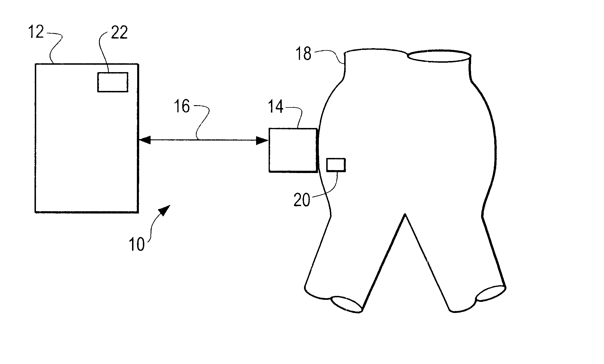
FIG. 1 depicts an ultrasonic system 10, generally, in accordance with an illustrated embodiment of the invention. The ultrasonic system 10 generally includes an ultrasonic power source 12, a transducer 14, a connector cable 16 and one or more thermal detectors 20.

Under the illustrated embodiment, an ultrasonic source (e.g., a generator) 12 generates a controlling electrical signal which is applied, through an attachment cable 16 to an ultrasonic transducer 14. The transducer 14 converts the electric signal into an ultrasound signal, which may then propagate into a portion 18 of a living human body.

The ultrasonic transducer 14 may be mechanically coupled to a probe for ultrasonic cutting or liposuction. In the alternative, the transducer 14 may also be an ultrasonic transceiver used for imaging.

Under the illustrated embodiment, the application of ultrasonic energy to the portion 18 is accompanied by the user of thermal indicators 20. The thermal indicators 20 may be attached to an ou...


PUM


Abstract

A method and apparatus are provided for applying an ultrasound treatment to a portion of a human body. The method includes the steps of determining a temperature rise which the body portion will experience when a dosage limit of the ultrasound treatment has been reached. The method further includes the steps of disposing on the body portion an indicator adapted to provide a visual change at the determined temperature and applying ultrasound to the body portion until the indicator provides the visual change at the determined temperature.

Description

1. Field of the InventionThe present invention relates to ultrasound and more particularly to ultrasound devices used for imaging, cutting or removal of tissue and / or matter from a living body.2. Description of Related ArtProbes or scalpels for the fragmentation and removal of materials, tissue and fluids from living beings are known to the art. For example, U.S. Pat. No. 2,227,727, issued Jan. 7, 1941 to Vincent Leggiardro, discloses an apparatus for fragmenting naturally formed stones, such as kidney stones, and the like, utilizing a high speed reciprocating rod which may have a blunt end, a sharp or chisel point, a cutting blade, or combination thereof, such as a cutting blade having a blunt end.A particular arrangement in an ultrasonically vibrated surgical tool using an irrigation fluid and an anti-coagulant is disclosed in U.S. Pat. No. 4,493,694, issued Jan. 15, 1985, to David G. Wuchinich, utilizes a hollow tool having a suction passage and at least one preaspirating orifice...

Claims


Application Information

Patent Timeline
Patent Type & Authority Patents(United States)
IPC IPC(8): A61B17/00A61B17/22A61N7/00
CPCA61B17/00A61B17/22004A61B2017/00084A61N7/00A61N2007/0008
Inventor HECHEL, DENNISEDLEMAN, WILLIAMSEGALIS, GENE
Owner MISONIX INC
Why Eureka
Try Eureka