Method and apparatus for suction anchor and mooring deployment and connection

a technology of suction anchors and moorings, which is applied in mechanical equipment, transportation and packaging, and vessel construction. it can solve the problems of heavy and bulky anchors and peripheral equipment that can swing, strike and damage other equipment in the immediate vicinity of the a-, and significant hazards to the safety of workers

Inactive Publication Date: 2002-10-01
DELMAR SYST
View PDF30 Cites 49 Cited by
  • Summary
  • Abstract
  • Description
  • Claims
  • Application Information

AI Technical Summary

Problems solved by technology

When a large A-frame type hoisting mechanism is utilized for lifting the anchor from the anchor handling vessel, particularly in rough sea conditions, the heavy and bulky anchor and its peripheral equipment may swing to and from and may strike and damage other equipment in the immediate vicinity of the A-frame type hoisting mechanism.
Additionally, since personnel will typically be required to ascend the A-frame type hoisting mechanism, such as to string wire rope and conduct other activities, the heavy swinging load of an anchor that is supported by the hoist constitutes and the movement of the A-frame hoist along with the vessel present significant hazards to the safety of workers whether present on the deck of the vessel or on the A-frame hoist or in the rigging of the hoist.
Another significant disadvantage of using two service vessels for anchor transportation, handling and deployment is simply the duplication of costs when two vessels are utilized rather than a single vessel.
Heretofore, the...

Method used


Image

  • Method and apparatus for suction anchor and mooring deployment and connection
  • Method and apparatus for suction anchor and mooring deployment and connection
  • Method and apparatus for suction anchor and mooring deployment and connection

Examples


Embodiment Construction

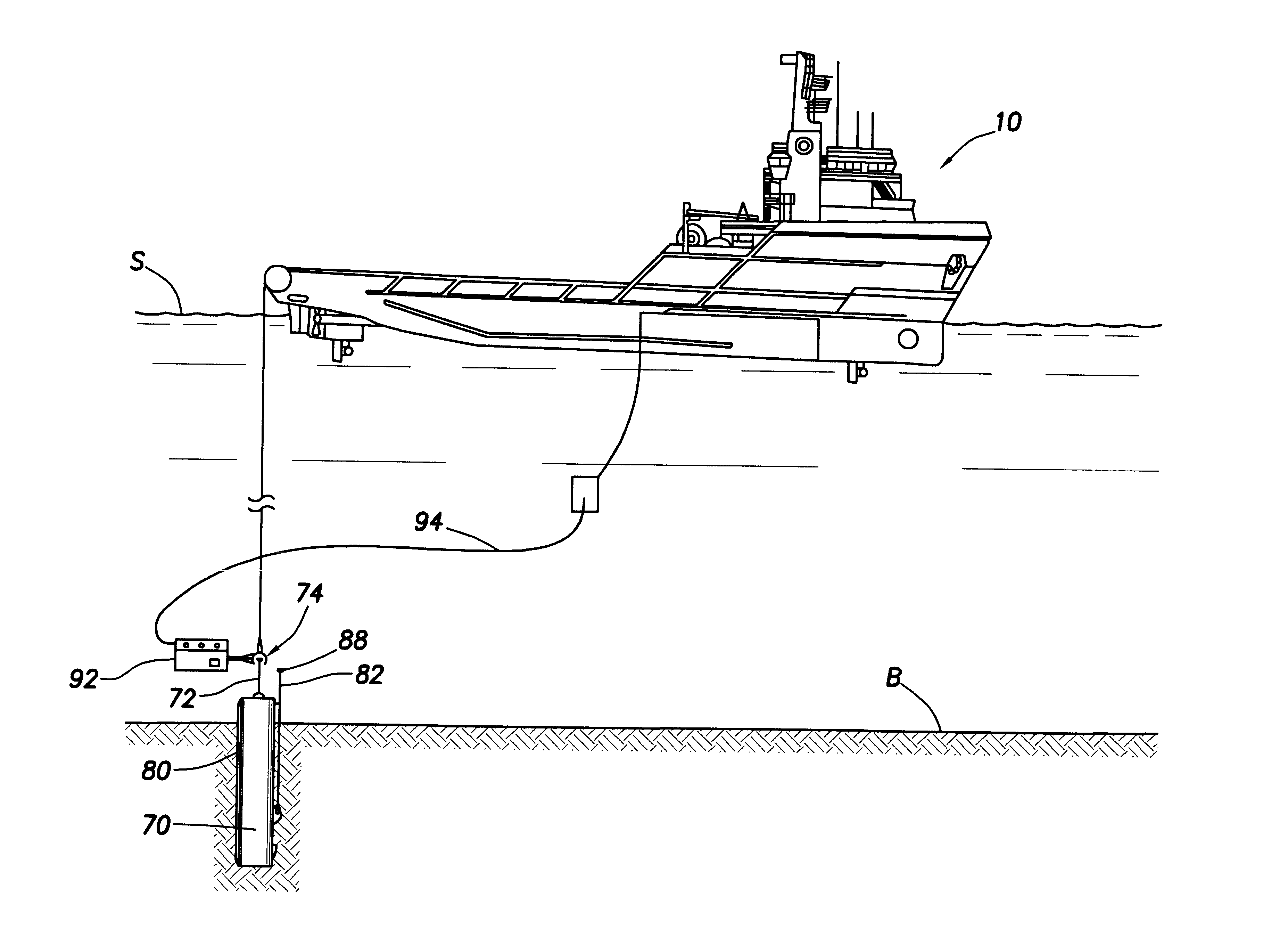
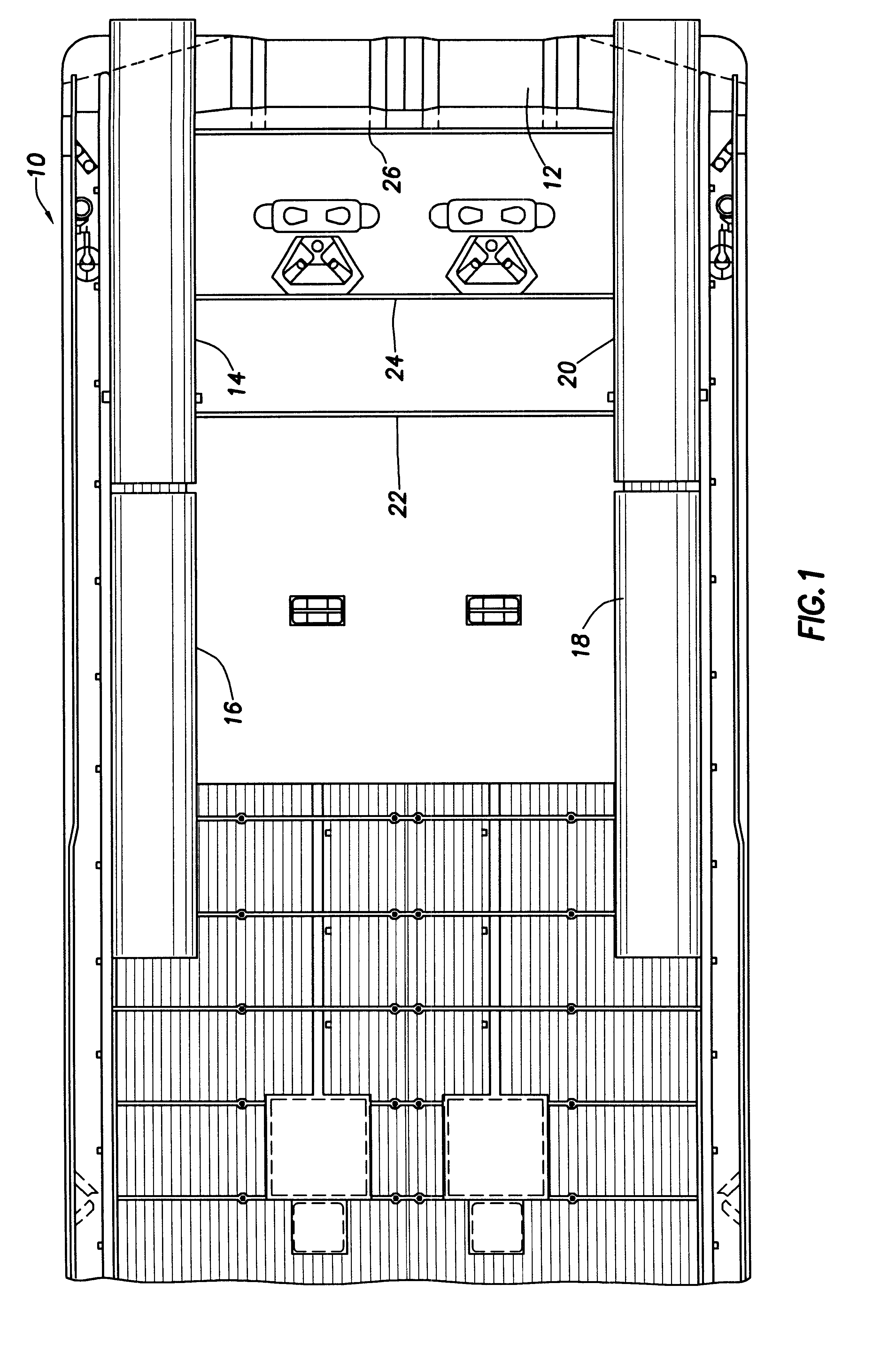
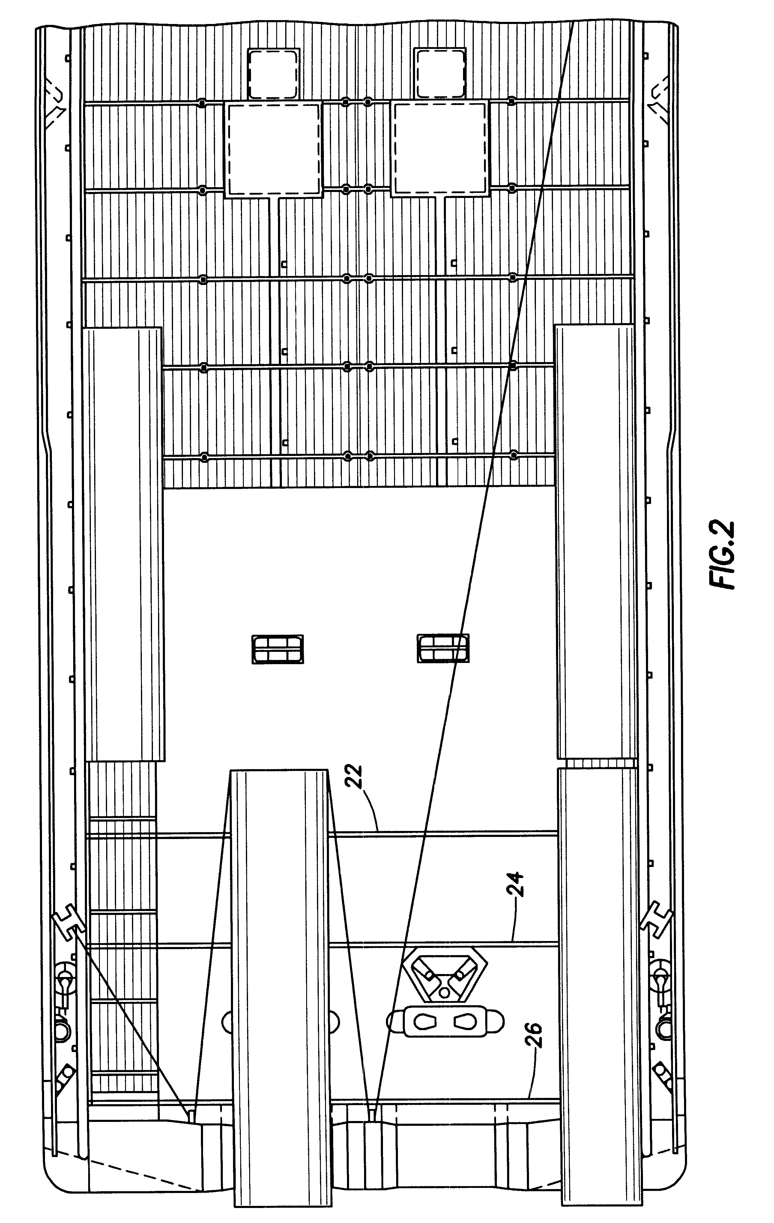
Referring now to the drawings and first to FIG. 1, the stem deck of an anchor handling vessel, also referred to therein to an anchor handling vessel, is shown generally at 10 and incorporates a stem roller 12 over which suction anchor piles and other apparatus is launched. The stem of the anchor handling vessel is pitted to receive 4 suction anchor piles shown at 14, 16, 18 and 20 which are secured to the anchor handling vessel by individual anchor handling assemblies which are shown in greater detail in FIGS. 3-6. The deck of the vessel is provided with transverse beams or rails 22, 24 and 26, one which being shown in FIG. 6 at 22. Track roller assemblies are provided as shown in FIGS. 3, 4 and 5 with one of the track roller assemblies, shown generally at 28 in FIG. 3, having parallel track members 30, 32 and 34 which are interconnected by transverse structural members 36. Roller assemblies 38 and 39 are mounted to the outer parallel structural members 30 and 34 and to the transver...


PUM


Abstract

A method and apparatus for deployment of mooring systems for buoyant marine structure such as mobile offshore drilling units (MODU's) and for connecting the same to the mooring lines thereof. An anchor handling vessel carries one or more anchors each having a deployment connection and a mooring connection and individually moves each anchor over its stern roller and deploys it to the sea bottom for installation. A handling line is disconnected by ROV from the deployment connection and is moved from the deployment connection to the mooring connection so as to become the main mooring line. Syntactic buoys are then mounted on the main mooring line for elevating it above the sea bottom for recovery. When MODU stationing is desired the anchor handling vessel then recovers the surface buoy and connects to the rig mooring line using a short section of mooring chain. A J-chaser stopper device is then installed in the mooring string and is connected to the mooring line of the MODU by a short section of chain. The J-chaser lowers the mooring string, completing the mooring connection between the anchor and the MODU. A plurality of mooring strings, typically eight, are deployed in this manner to properly station the MODU. Disconnection of the MODU is accomplished essentially by the reverse of the above deployment procedure.

Description

1. Field of the InventionThis invention relates generally to mooring line connections for subsea operations, particularly for suction anchor pile moorings. More particularly, this invention concerns a wire socket connector mechanism which facilitates subsea connection and reconnection of mooring lines of semi-submersible drilling rigs, production and drilling platforms and the like to suction anchor piles and other anchor devices. This invention also concerns deployment and installation of suction anchor piles and a mooring wire assembly with retrieval buoys and sling on one of its ends. The invention also concerns addition of buoys to mooring wire sections and connecting the mooring wire to a vessel to be moored. The procedure also concerns the mooring wire, buoy recovery, wire retrieval and suction anchor pile recovery and a procedure for recovering mooring wires and other apparatus.2. Description of the Prior ArtPresent procedures for installing subsurface anchors and establishin...

Claims


Application Information

Patent Timeline
IPC IPC(8): B63B21/27B63B21/00B63B21/50B63B21/24B63B21/04F16G11/14F16G11/00
CPCB63B21/04B63B21/27B63B21/50F16G11/00F16G11/14
Inventor BERGERON, BILLY J.
Owner DELMAR SYST
Why Eureka
Try Eureka