Cam retaining means for ZIF electrical connector

a technology of cam retaining and zif, which is applied in the direction of coupling contact members, coupling device connections, electrical apparatus construction details, etc., can solve the problems of relatively less stable engagement between pins and respective terminals, slide plates are susceptible to a problem known as "kickback"

Inactive Publication Date: 2002-10-01
MOLEX INC
View PDF3 Cites 7 Cited by
  • Summary
  • Abstract
  • Description
  • Claims
  • Application Information

AI Technical Summary

Problems solved by technology

However, the type of sliding means in which the cam member is inserted through the base housing and the slide plate is susceptible to a problem known as "kickback."
Also, the kickback force tends to move the slide plate back towards the first insertion position, thereby make the engagement between the pins and the respective terminals relatively less stable.

Method used


Image

  • Cam retaining means for ZIF electrical connector
  • Cam retaining means for ZIF electrical connector
  • Cam retaining means for ZIF electrical connector

Examples


Embodiment Construction

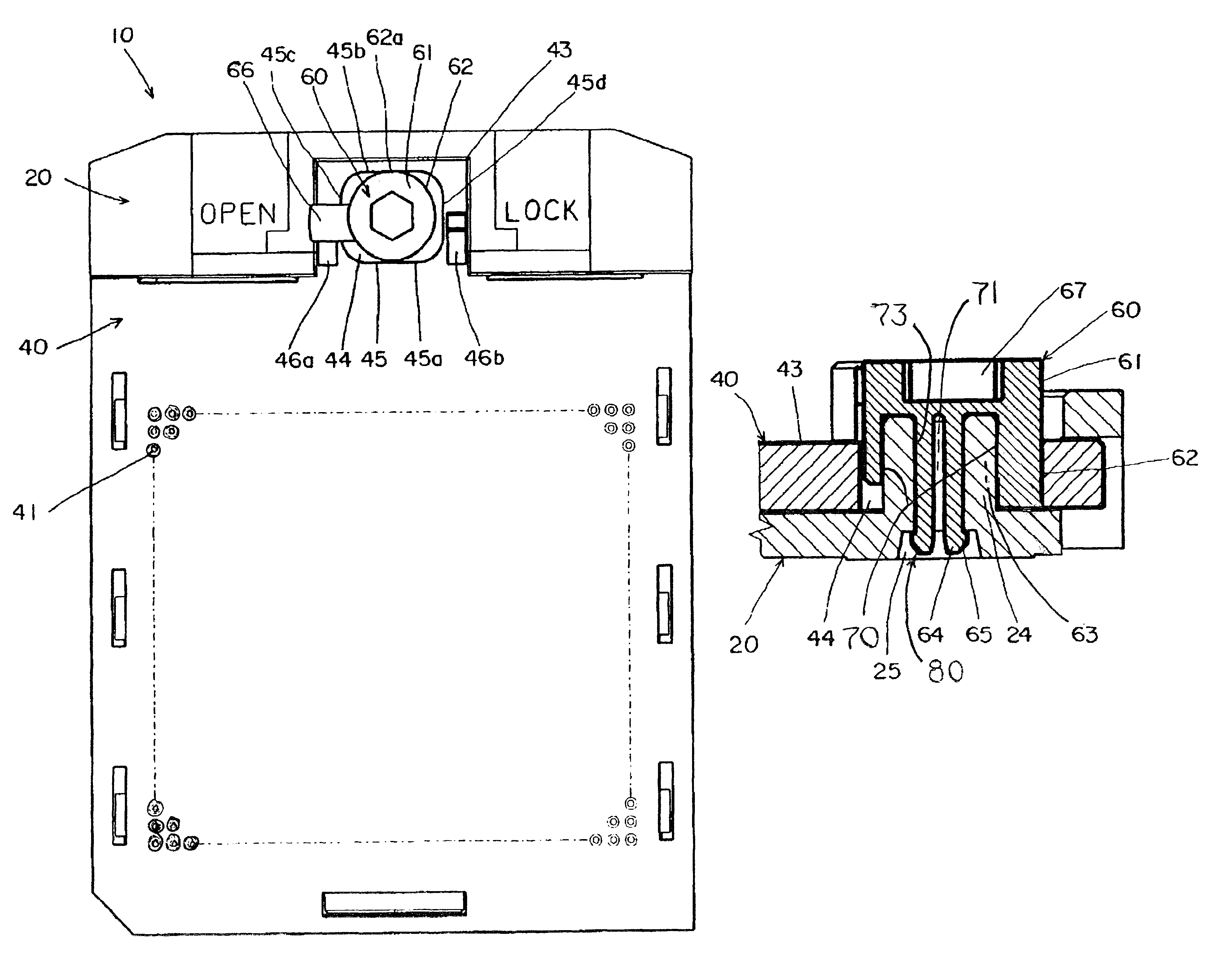
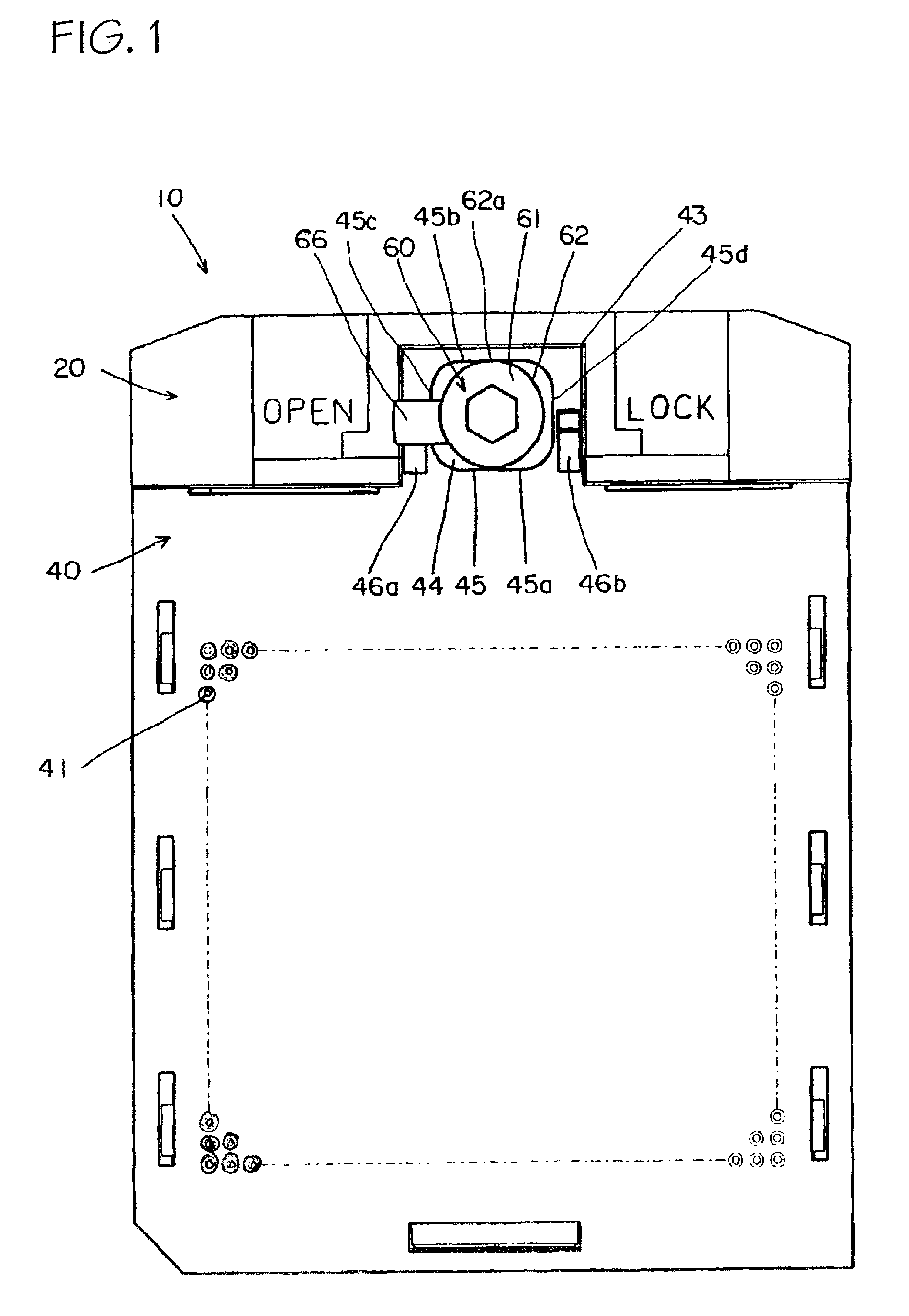
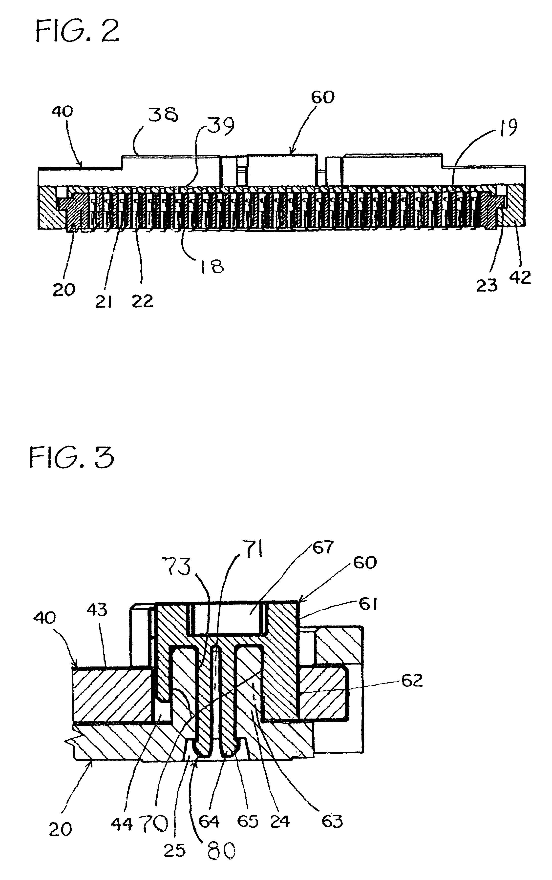
In a preferred embodiment, the invention is an electrical connector 10 for a pin grid array package as shown in FIG. 1. The electrical connector 10 comprises a generally planar and quadrangular shaped base housing 20 and a generally planar and quadrangular shaped slide plate 40 overlaid on the interior side of base housing 20. A plurality of terminals 21 shown in FIG. 2 are mounted in grid array 26 fashion on base housing 20. Tails 22 extend from each the terminals 21 and are arranged on the bottom surface of base housing 20. A mounting portion of each of the terminals 21 is open for receiving a pin of a PGA package (not shown).

Slide plate 40 is formed with through holes 41 in grid array 30 fashion generally corresponding to the terminals 21. Each of two guide projections 23 formed on opposite edges of the base housing 20 mates with one of generally L-shaped edge plates 42. The edge plates 42 extend downwardly from the edges of the slide plate 40, so that the slide plate 40 is adapt...


PUM


Abstract

A electrical connector for a pin grid array package includes a base housing for mounting a plurality of terminals in grid array fashion, and a slide plate formed with through holes in grid array fashion corresponding to each of the terminals and overlaid on the upper side of the base housing. The slide plate slides between a position in which a pin of the pin grid array package is held adjacent to one of the terminals position and a position in which the pin is engaged with the terminal. A cam member is inserted through a cam opening formed in the slide plate and rotatably supported on the base housing so that a cam surface and an opening edge are mutually opposed. Engaging means rotatably secure the cam member in proper axial position with respect to the base housing. A flat surface formed on the cam surface abuts a straight edge formed on the cam opening when the slide plate is in the position in which the pin is engaged with the terminals.

Description

The present invention relates generally to an electrical connector or socket for a pin grid array package.DESCRIPTION OF THE RELATED ARTTypically, an electrical connector for a pin grid array ("PGA") package comprises a base housing for mounting a plurality of terminals in grid array fashion, and a slide plate formed with through holes in grid array fashion corresponding to the respective terminals and overlaid on the interior side of the base housing. The slide plate is adapted for sliding between a first insertion position and a second engagement position. In the first insertion position, the pins of the PGA package can be inserted adjacent to, but without engaging, the respective terminals with relatively small or zero insertion force. In the second engagement position, the pins are engaged with the respective terminals.Sliding means or actuators for the slide plate are well known. One type of previously published sliding means includes a cam shaft mounted along the rear edge of ...

Claims


Application Information

Patent Timeline
Patent Type & Authority Patents(United States)
IPC IPC(8): H01R13/193H01R13/02H05K7/10H01L23/32H01R33/76H01R33/97
CPCH01R13/193H05K7/1007
Inventor HIRATA, TOSHIHISA
Owner MOLEX INC
Why Eureka
Try Eureka