
Multipurpose clamper for bonding machine worktable
A workbench and multi-purpose technology, applied in the direction of electrical components, semiconductor/solid-state device manufacturing, circuits, etc., can solve problems such as small adsorption force, insufficient clamping strength, failure, etc., to reduce design and processing, reduce production costs, The effect of improving productivity
- Summary
- Abstract
- Description
- Claims
- Application Information
AI Technical Summary
Problems solved by technology
Method used
Image

Examples
Embodiment Construction
[0012] Below the present invention will be further described in conjunction with the embodiment in the accompanying drawing:
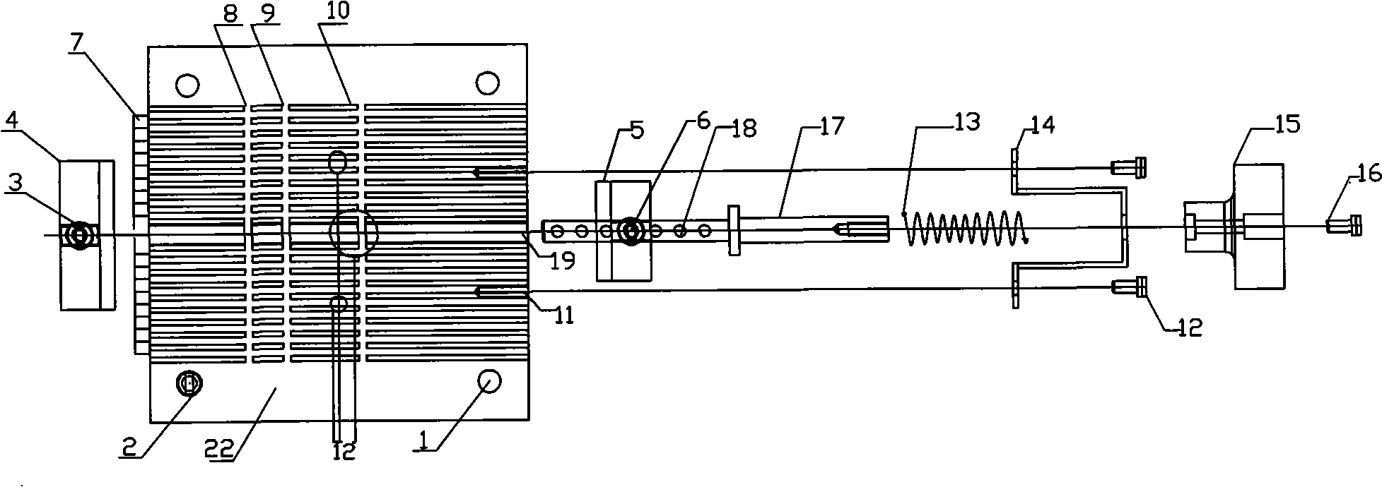
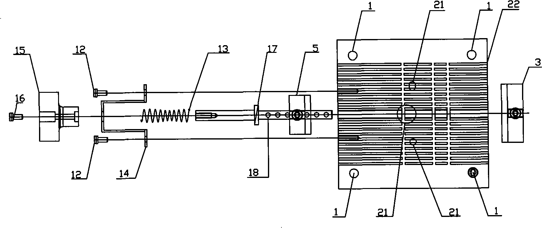
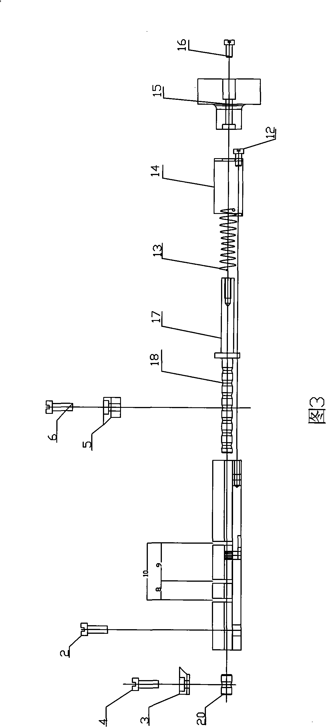
[0013] Such as figure 1 ~As shown in Figure 3, it includes the connection hole 1 of the bonding machine table, the fixing screw 2 of the bonding machine table, the first upper bevel clamping pressure piece 3, the fixing screw 4, and the second upper bevel clamping Pressing plate 5, fixing screw 6, first fixing groove 7, second fixing groove 8, third fixing groove 9, fourth fixing groove 10, fixing hole 11, fixing screw 12, compression spring 13, compression spring stopper Block 14, compression spring handle 15, spring handle locking screw 16, sliding rod 17, positioning distance adjustment hole 18, chute 19, adjustable positioning block 20, fixture loading positioning hole 21 and fixture body 22, etc.
[0014] The present invention mainly adopts that a chute 19 is provided on the fixture body 22 , and the chute 19 is used for sliding the sliding rod 1...
PUM
 Abstract
Description
Claims
Application Information