Impact sensor assembly for an automotive vehicle and a method of forming the same

Inactive Publication Date: 2002-10-08
GM GLOBAL TECH OPERATIONS LLC
View PDF14 Cites 13 Cited by
  • Summary
  • Abstract
  • Description
  • Claims
  • Application Information

AI Technical Summary

Problems solved by technology

However, vehicle body designs change over time and such design changes may change the preferred positions within a vehicle to place a sensor assembly.
Changing such sensor assembly designs can be costly.

Method used


Image

  • Impact sensor assembly for an automotive vehicle and a method of forming the same
  • Impact sensor assembly for an automotive vehicle and a method of forming the same
  • Impact sensor assembly for an automotive vehicle and a method of forming the same

Examples


Embodiment Construction

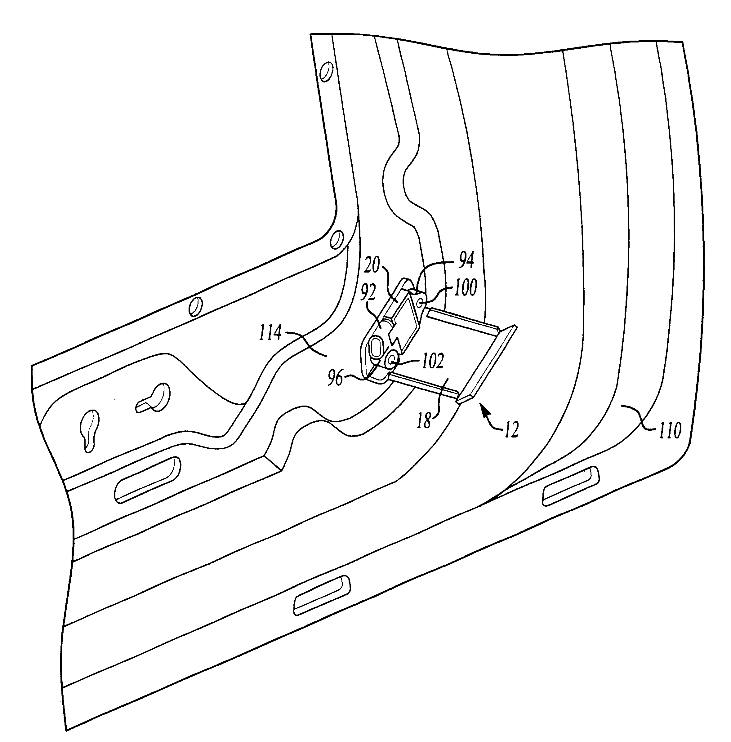
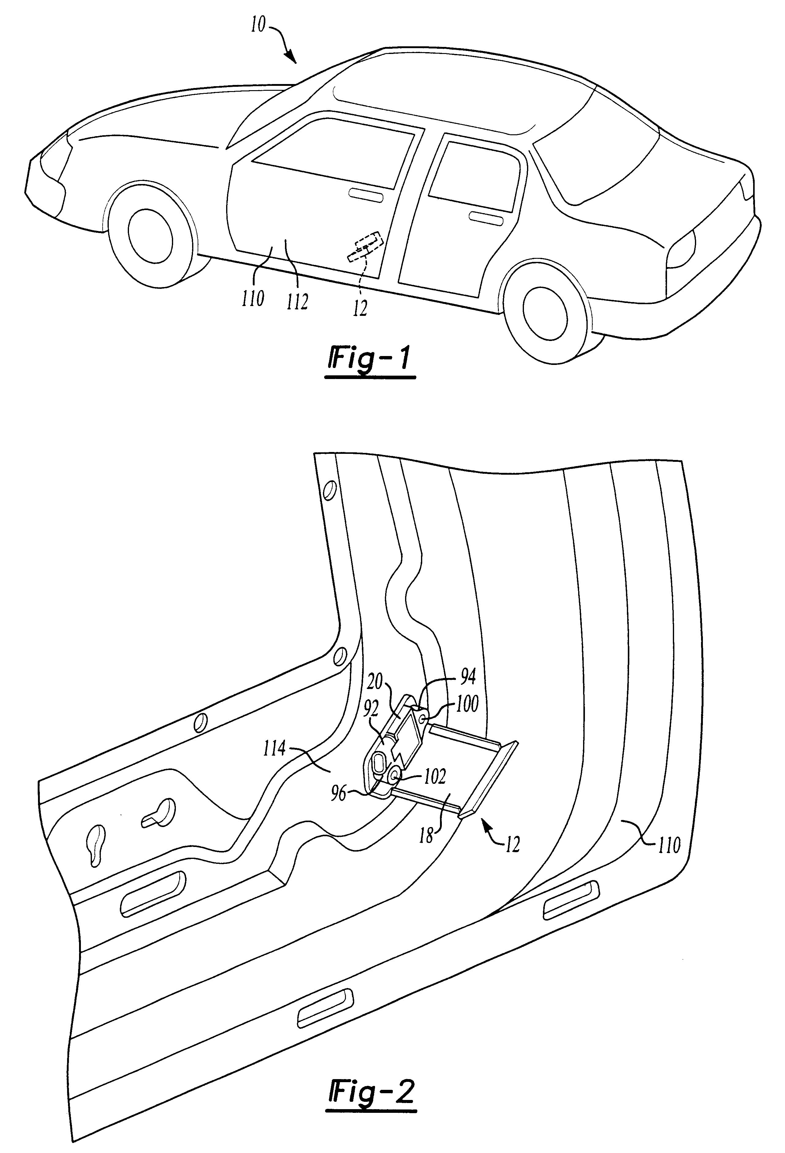
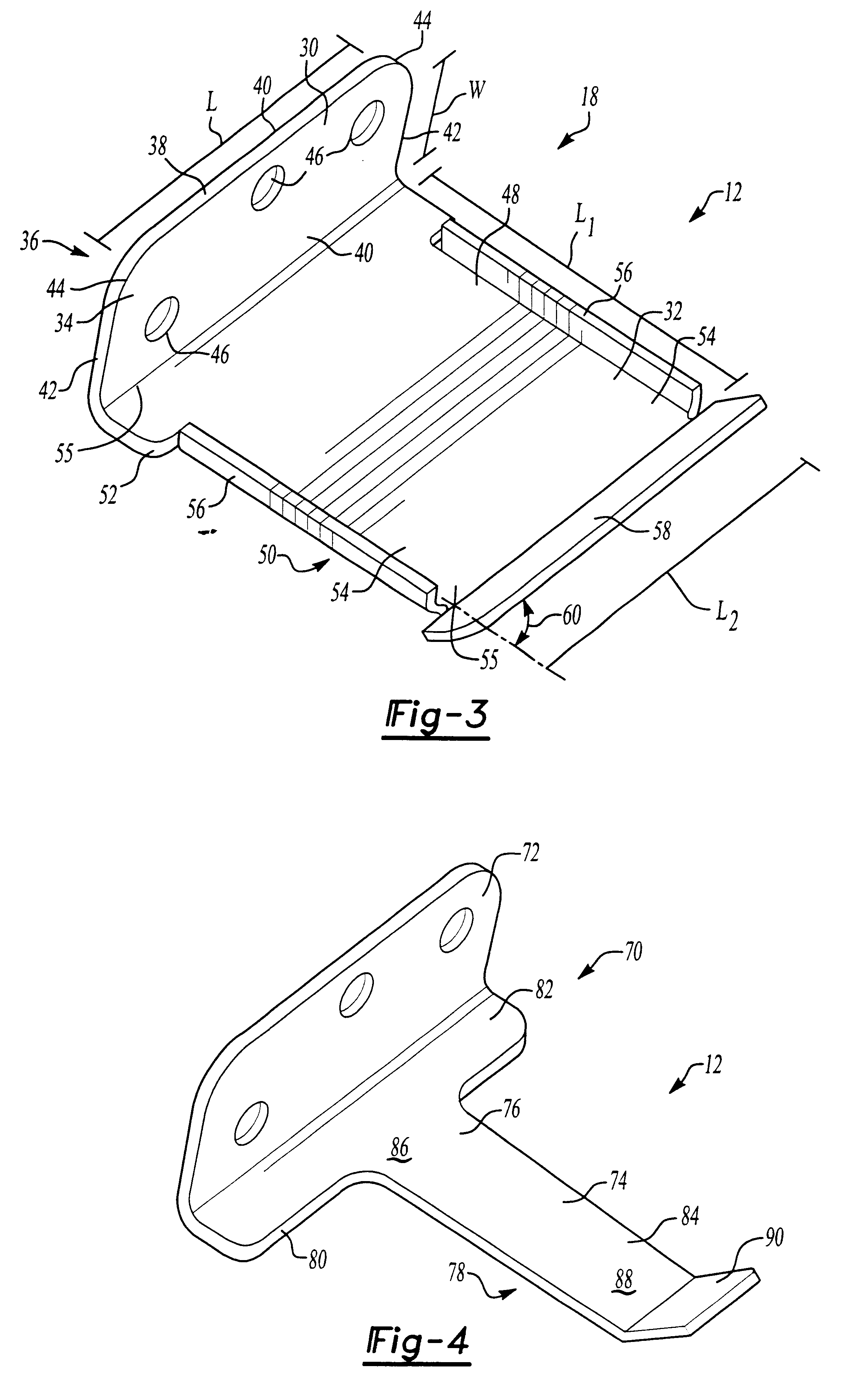
The present invention relates to an impact sensor assembly that has particular application for use in an automotive vehicle. The impact sensor assembly generally includes a sensor operatively adjacent a bracket, and the bracket includes a portion that extends away from the sensor toward an outer panel or other portion of a body of the vehicle for fine tuning the sensitivity of the sensor or for adapting the sensor assembly for placement at a particular position within the vehicle. In a non-limiting embodiment, the sensor assembly may be in communication with a controller or other unit and may send signals to the controller or other unit based upon phenomena sensed. Such phenomena may include, but is not limited to, force, acceleration, deceleration, velocity, crush or other phenomena caused by impact of the vehicle with another object. The controller may then signal the activation of another item within the vehicle such as a side impact air bag.

Referring now to FIGS. 1 and 2, there ...


PUM


Abstract

An impact sensor assembly that has particular utility in automotive vehicles is disclosed. The assembly includes an impact sensor and a bracket that is placed operatively adjacent the sensor. The bracket includes a portion extending away from the sensor for extending the sensing area of the sensor.

Description

TECHNICAL FIELDThe present invention relates to an impact sensor assembly that includes an impact sensor and a bracket operatively adjacent the impact sensor. More particularly, the present invention relates to an impact sensor assembly having an impact sensor and a bracket operatively adjacent the impact sensor wherein the bracket includes a portion extending away from the sensor toward an outer portion of an automotive vehicle.BACKGROUND OF THE INVENTIONImpact sensors or sensor assemblies are often placed within or upon an automotive vehicle to sense phenomena caused by an impact force on the vehicle structure. Generally impact sensor assemblies send a signal to a controller or other unit based upon the phenomena sensed. Such phenomena sensed by these sensor assemblies include, but are not limited to, acceleration, deceleration, force, velocity, crush or other phenomena. In many cases, these sensor assemblies are mounted adjacent an outer panel or other outer portion of the vehicl...

Claims


Application Information

Patent Timeline
IPC IPC(8): B60R21/01
CPCB60R21/013B60R2021/01006
Inventor KLEINBERG, RAYMOND
Owner GM GLOBAL TECH OPERATIONS LLC
Why Eureka
Try Eureka