Method of thermal management for a hybrid vehicle

a hybrid vehicle and thermal management technology, applied in the direction of engines/engines, propulsion parts, machines/engines, etc., can solve the problem of reducing the amount of waste heat available for us

Inactive Publication Date: 2002-10-15
VISTEON GLOBAL TECH INC
View PDF11 Cites 161 Cited by
  • Summary
  • Abstract
  • Description
  • Claims
  • Application Information

AI Technical Summary

Problems solved by technology

Vehicles, and in particular automotive vehicles have traditionally been powered by a heat engine using a petroleum-based fuel, because of its ready availability and rel

Method used


Image

  • Method of thermal management for a hybrid vehicle
  • Method of thermal management for a hybrid vehicle
  • Method of thermal management for a hybrid vehicle

Examples


Embodiment Construction

)

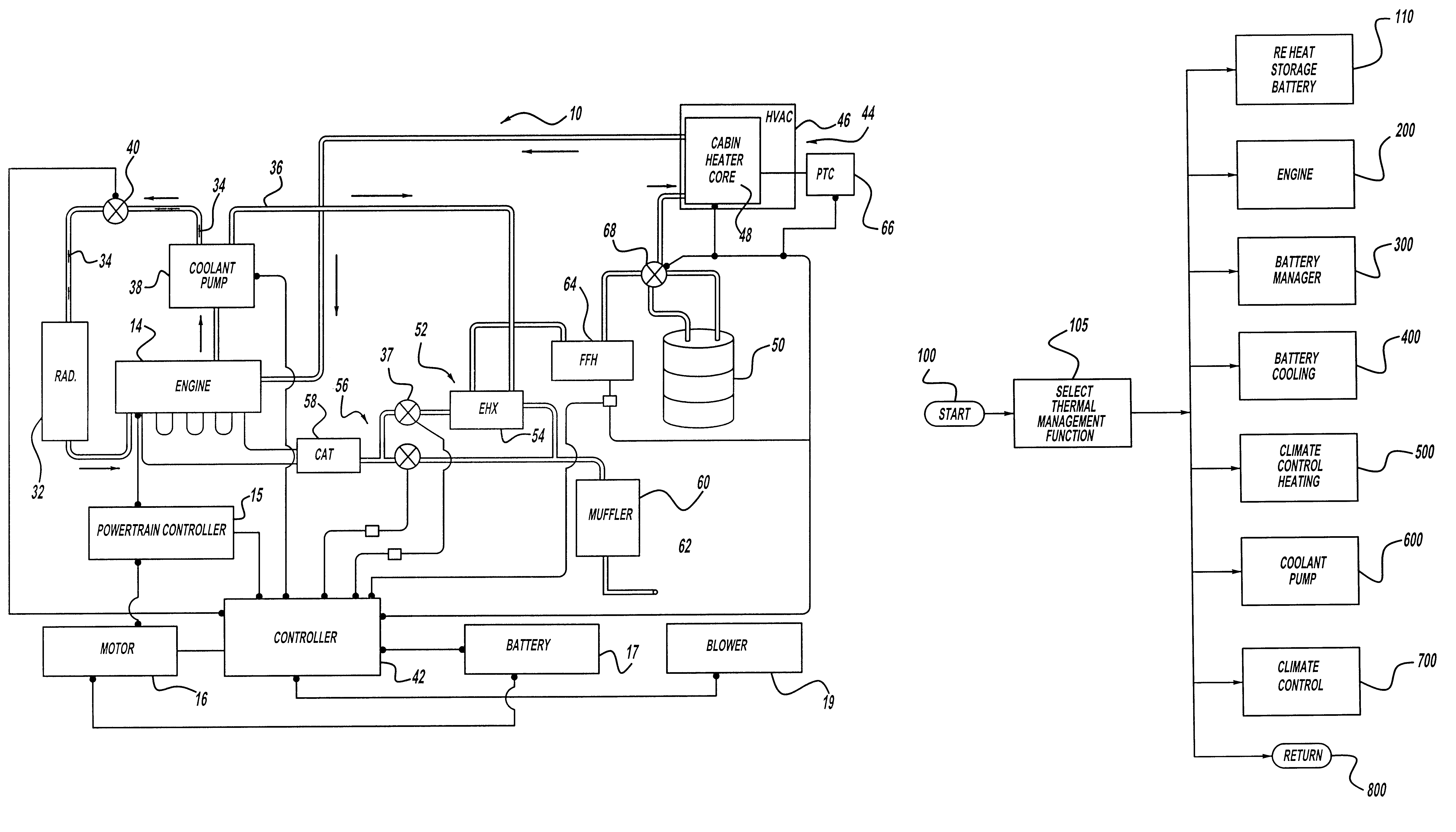
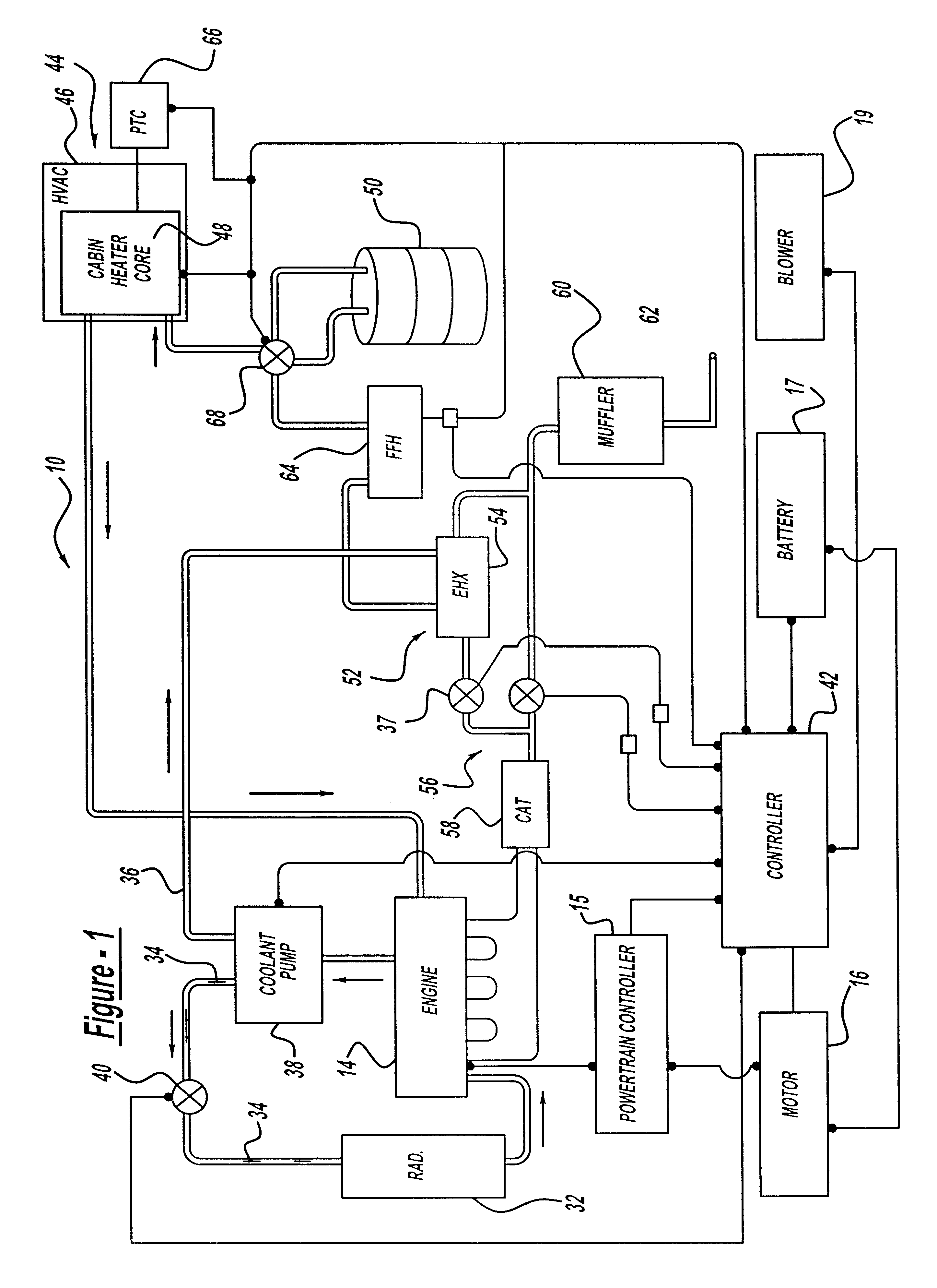
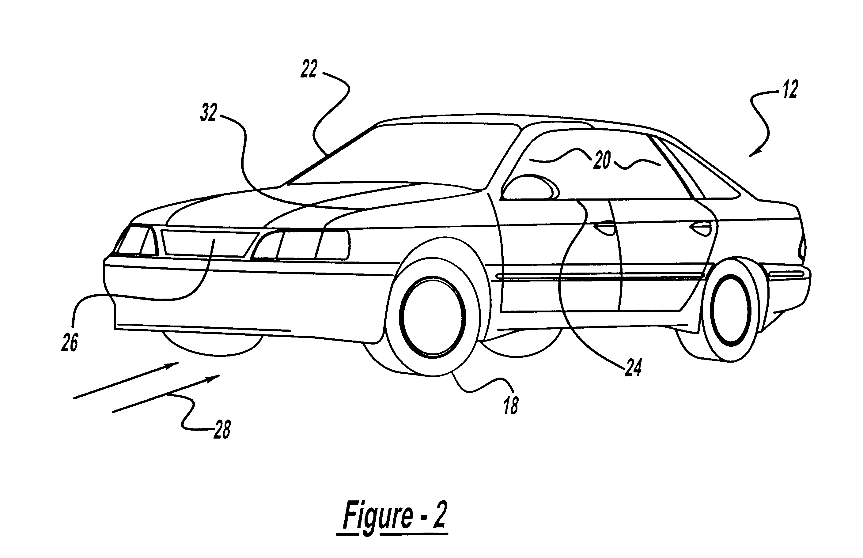
Referring to FIGS. 1 and 2, one embodiment of a thermal management system 10 on a hybrid vehicle 12 is illustrated. Preferably, the hybrid vehicle 12 includes a heat engine 14 operating on a hydrocarbon-based or fossil fuel and an electric machine 16, although other vehicle types are contemplated. In this example, the electric machine 16 is an induction motor or permanent magnet motor capable of providing both positive and regenerative torque, by functioning both as a motor and an alternator. Electric power to operate the electric machine is stored in an electric power storage battery 17. The engine 14 is operatively connected to a transmission (not shown), as is known in the art, to transmit engine rotation and power to a drive wheel 18. Thus, the transmission enables the hybrid vehicle 12 to accelerate over its speed range through predetermined gear ratios, while the engine 14 functions within a predetermined operating range. It should be appreciated that the engine 14 and motor ...


PUM


Abstract

A method of thermal management for a thermal management system in a vehicle includes the steps of selecting a thermal management function. The method also includes the steps of adjusting a temperature within the thermal management system using the thermal management function and using the adjusted temperature within the thermal management system to control a temperature within an occupant compartment of the vehicle.

Description

1. Field of the InventionThe present invention relates generally to thermal management in a vehicle and, more specifically, to a method of thermal management for a hybrid vehicle.2. Description of the Related ArtVehicles, and in particular automotive vehicles have traditionally been powered by a heat engine using a petroleum-based fuel, because of its ready availability and relative cost. Although gasoline is currently the fuel of choice for most automotive vehicles, recent environmental concerns have resulted in increasingly more stringent Federal and State emission regulations. As a result, alternative fuel sources have been contemplated for automotive vehicles. For example, methanol, ethanol, natural gas, electricity or a combination of these fuels have been considered as potential fuel sources.A hybrid vehicle, as is known in the art, is powered by a renewable and a non-renewable energy source. The hybrid vehicle overcomes the technical disadvantages of a dedicated electric vehi...

Claims


Application Information

Patent Timeline
IPC IPC(8): B60H1/00F01P11/20F01P11/14F01P3/20H01M10/50H01M10/42B60K1/04B60H1/22B60K11/04B60L50/16F01N5/02F01P1/06F01P3/12F01P7/02F01P7/16
CPCB60H1/004B60H1/00492B60H1/00735B60H1/032B60H1/2206F01P3/20F01P11/20H01M10/5004H01M10/5016H01M10/5022H01M10/5063H01M10/5075H01M10/5095F01P2011/205F01P2050/24F01P2060/08H01M10/613H01M10/625H01M10/633H01M10/6561H01M10/6567H01M10/663Y02E60/10
Inventor DAGE, GERHARD ALLENSMITH, LAWRENCE WILLIAM
Owner VISTEON GLOBAL TECH INC
Why Eureka
Try Eureka