Dual function inboard barrier/bridgeplate assembly for wheelchair lifts

a technology of inboard barrier and bridge plate, which is applied in the direction of transportation items, loading/unloading vehicle arrangment, refuse collection, etc., can solve the problems of cable fraying or breaking in use, difficult to precisely adjust the cable, and requiring frequent readjustments

Inactive Publication Date: 2002-10-15
BRAUN THE
View PDF17 Cites 15 Cited by
  • Summary
  • Abstract
  • Description
  • Claims
  • Application Information

AI Technical Summary

Benefits of technology

In a typical Braun-type parallelogram-type lift, such as described in aforesaid application Ser. No. 08/843,497, the longer, lower push arm is pivoted to the platform at a location somewhat inboard of the platform pivot which supports the platform from the lifting arm extension of the parallelogram outer link. The distance between these pivots provides a lever arm, such that as the push arm is pressed down, the platform is caused to be rotated upwards to a stowed position. The push arm is braced by the shorter upper brace arm, both of which are coaxially pivoted to the sl...

Problems solved by technology

Cable systems however have a number of serious drawbacks, among them being that the cable is difficult to adjust precisely, thereby requiring frequent readjustments, as it stretches in use and tends to lengthen or shorten with temperature.
In addition, a cable can fray or break in ...

Method used


Image

  • Dual function inboard barrier/bridgeplate assembly for wheelchair lifts
  • Dual function inboard barrier/bridgeplate assembly for wheelchair lifts
  • Dual function inboard barrier/bridgeplate assembly for wheelchair lifts

Examples


Embodiment Construction

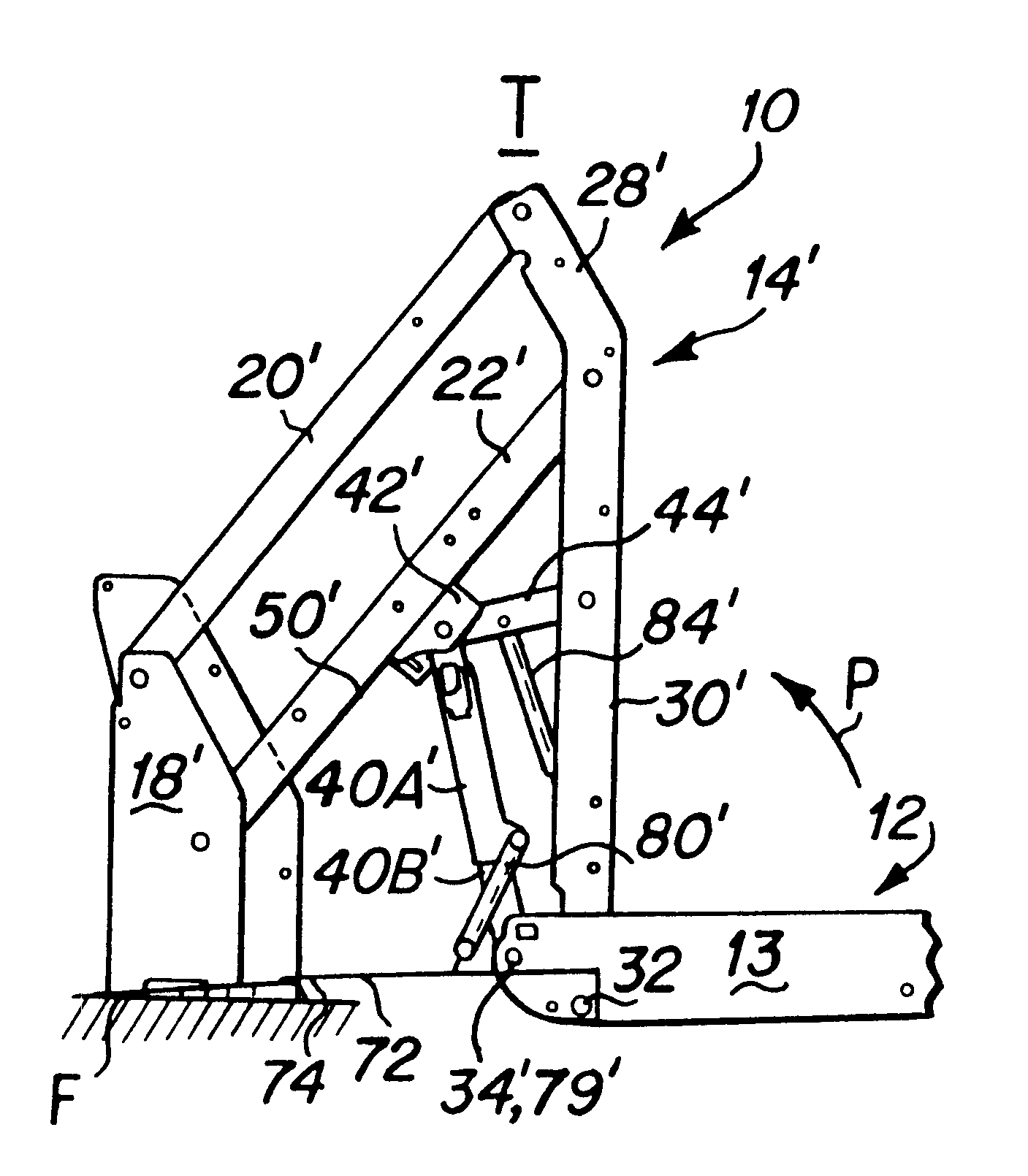
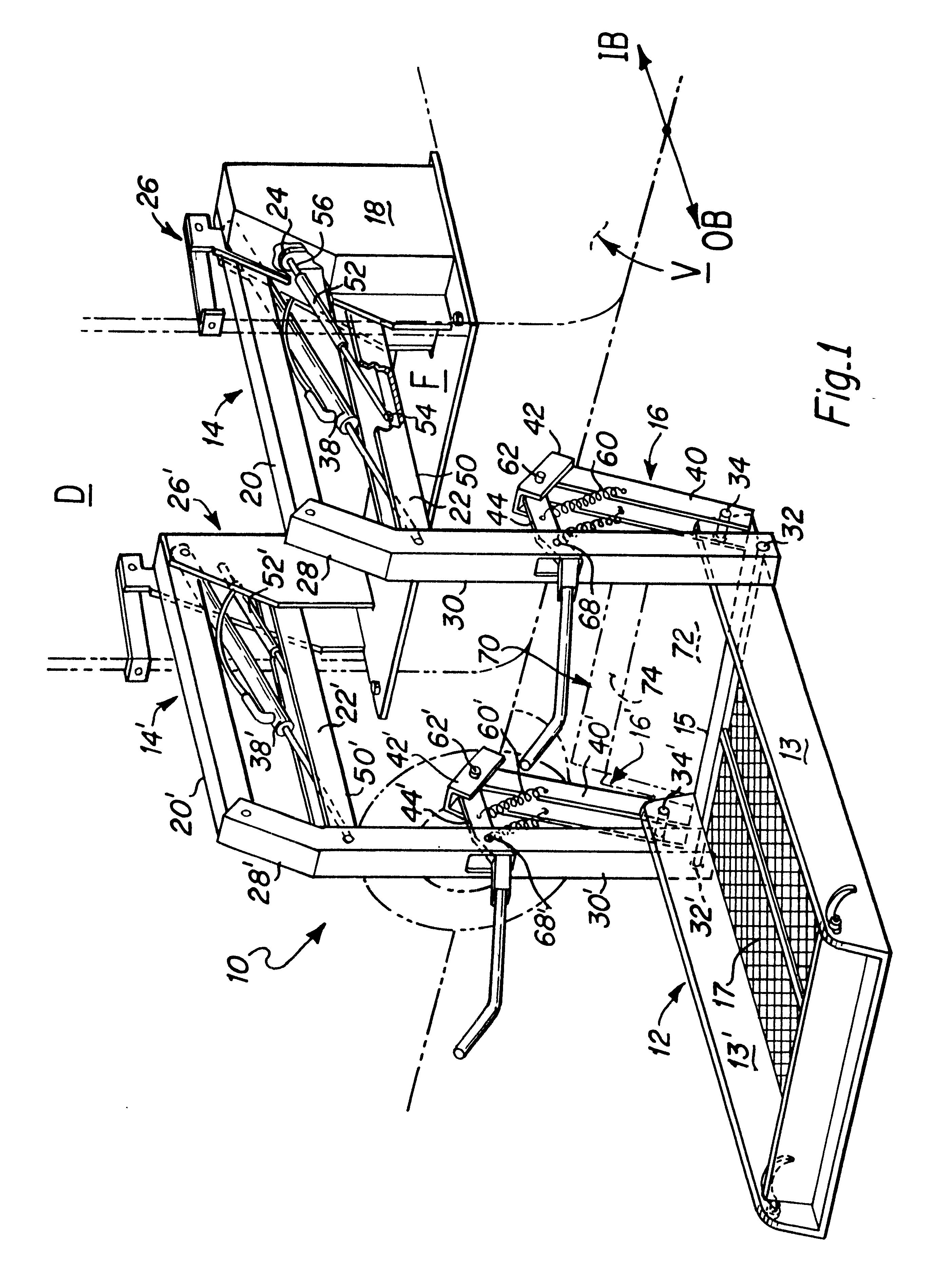
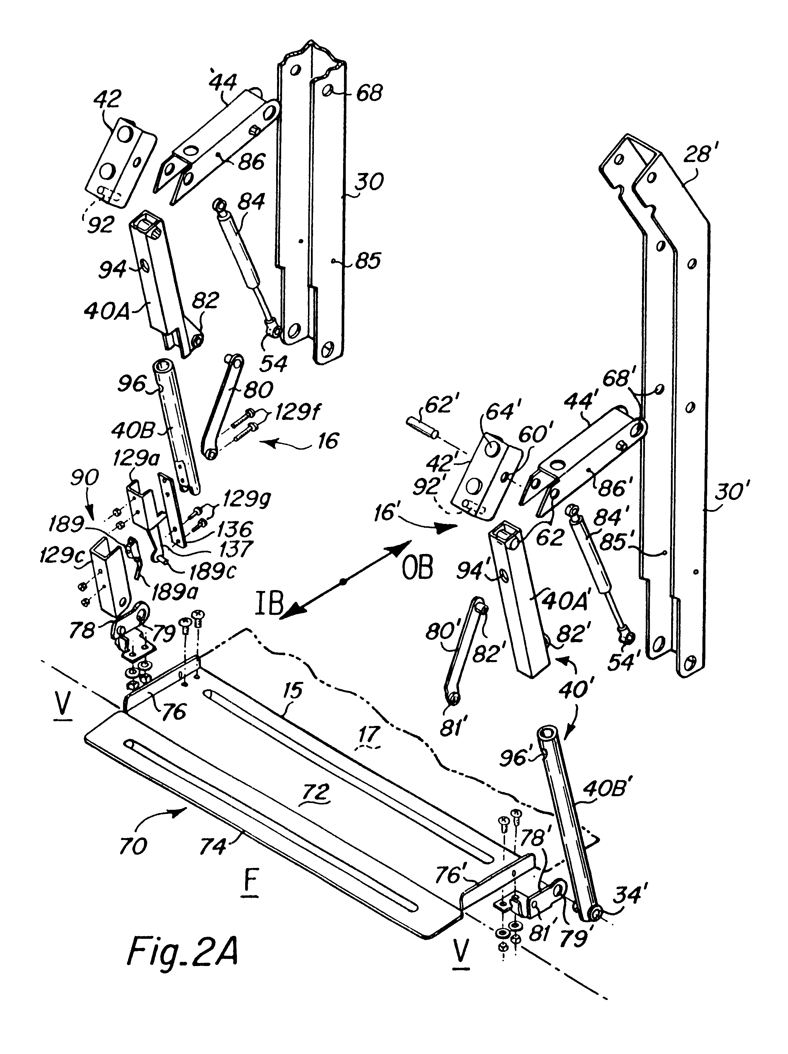
The following detailed description illustrates the invention by way of example, not by way of limitation of the principles of the invention. This description will clearly enable one skilled in the art to make and use the invention, and describes several embodiments, adaptations, variations, alternatives and uses of the invention, including what is presently believed to be the best mode of carrying out the invention.

In this regard, the invention is illustrated in the several figures, and is of sufficient complexity that the many parts, interrelationships, and sub-combinations thereof simply cannot be fully illustrated in a single patent-type drawing. For clarity and conciseness, several of the drawings show in schematic, or omit, parts that are not essential in that drawing to a description of a particular feature, aspect or principle of the invention being disclosed. Thus, the best mode embodiment of one feature may be shown in one drawing, and the best mode of another feature will ...


PUM


Abstract

A dual function, inboard barrier/bridgeplate assembly for wheelchair lifts having a stowable platform, the barrier being pivotably secured to the inboard end of the lift platform, which barrier is actuated by a link to variously raise the barrier to a safety position and lower it to a bridging position in accordance with the position of the platform. The dual function barrier/bridgeplate system is particularly useful in combination with a parallelogram type lift employing an articulated lever assembly having a sliding block for leveraging the platform from a horizontal transfer orientation to a vertical, or over-vertical stowage position. There is disclosed a barrier assembly in which a spring assist system comprising a gas spring acting on one member of the articulated lever assembly and a lever arm linking a second arm of the articulated lever assembly to the barrier co-operate to actuate the barrier from a raised position when the platform is away from the transfer level and a lowered position to act as a bridge plate at the transfer level. A telescoping push arm is included which actuates the barrier by means of a pivoted link which rotates the barrier in response to the telescoping motion of the push arm. A safety interlock and load detecting system may be employed to prevent the platform from moving to the stowed position when a load greater than a predetermined weight is on the platform. An anti-free fall mechanism is disclosed comprising a pin in the slide block which engages mating slots in the telescoping push arm members to lock their length during the initial stage of deploy of the platform downwardly from the vertical stowed position.

Description

This application relates to wheelchair lifts having a stowable platform and a dual function safely barrier pivotably secured to the inboard end thereof, which barrier is actuated by a link to variously raise the barrier to a safety position and lower it to a bridging position in synchrony with the position of the platform. More particularly the invention relates to dual parallelogram type lifts employing an articulated lever assembly having a sliding block for leveraging the platform from a horizontal transfer orientation to a vertical, or over-vertical stowage position, in which a spring assist system comprising a gas spring acting on one member of the articulated lever assembly and a lever arm linking a second arm of the articulated lever assembly to the barrier co-operate to actuate the barrier from a raised position when the platform is away from the transfer level to a lowered position to act as a bridge plate at the transfer level. Also disclosed is an anti-free fall assembly ...

Claims


Application Information

Patent Timeline
IPC IPC(8): A61G3/00A61G3/06
CPCA61G3/06A61G3/062Y10S414/134
Inventor DUPUY, JAMES ROBERTBUDD, ALFRED L.PIERROU, JAMES R.WOLFF, BARRY E.
Owner BRAUN THE
Why Eureka
Try Eureka