Particle measurement apparatus flow cell useful for sample fluids having different refractive indexes

a flow cell and particle measurement technology, applied in the field of flow cells, can solve the problems of increasing noise, inaccurate detection of particle information, and increasing nois

Inactive Publication Date: 2002-10-15
RION COMPANY
View PDF3 Cites 20 Cited by
  • Summary
  • Abstract
  • Description
  • Claims
  • Application Information

AI Technical Summary

Problems solved by technology

Accordingly, there is a problem that particle information, including a particle diameter and so on, cannot be detected accurately, due to the the difference in the kinds of sample fluids being analyzed.
Therefore, there a

Method used


Image

  • Particle measurement apparatus flow cell useful for sample fluids having different refractive indexes
  • Particle measurement apparatus flow cell useful for sample fluids having different refractive indexes
  • Particle measurement apparatus flow cell useful for sample fluids having different refractive indexes

Examples


first embodiment

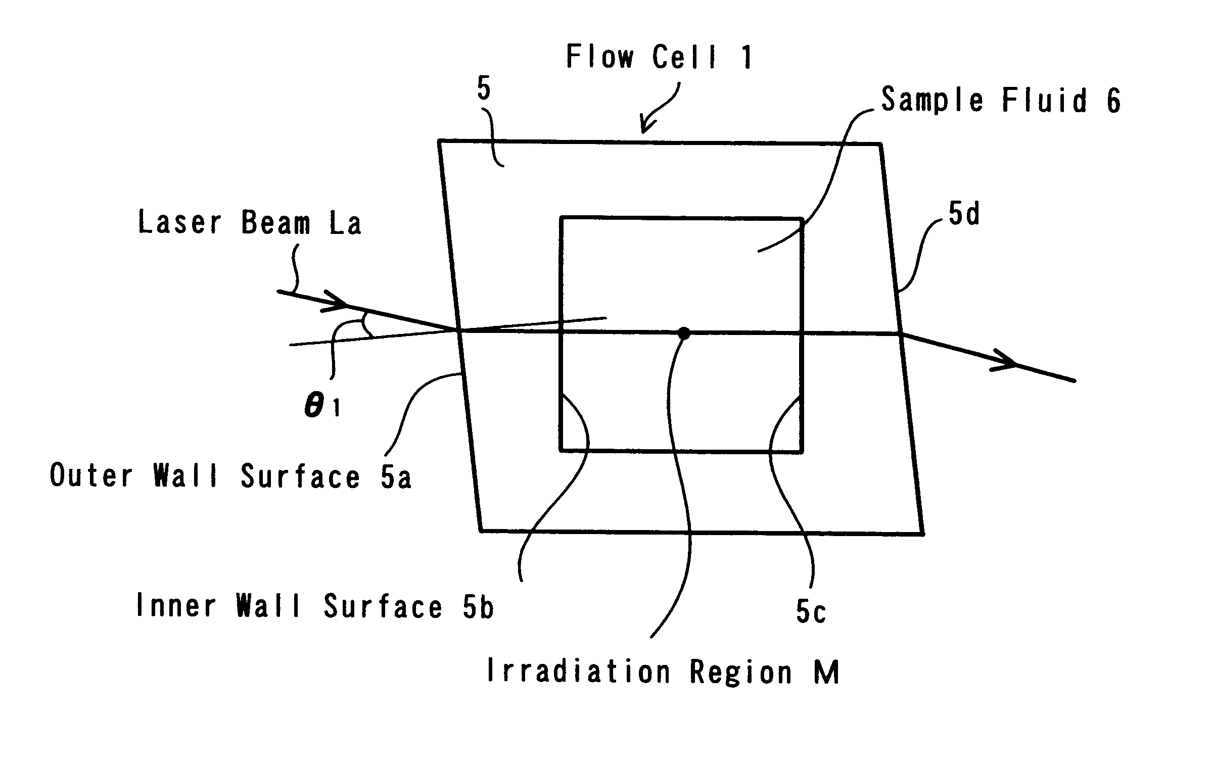
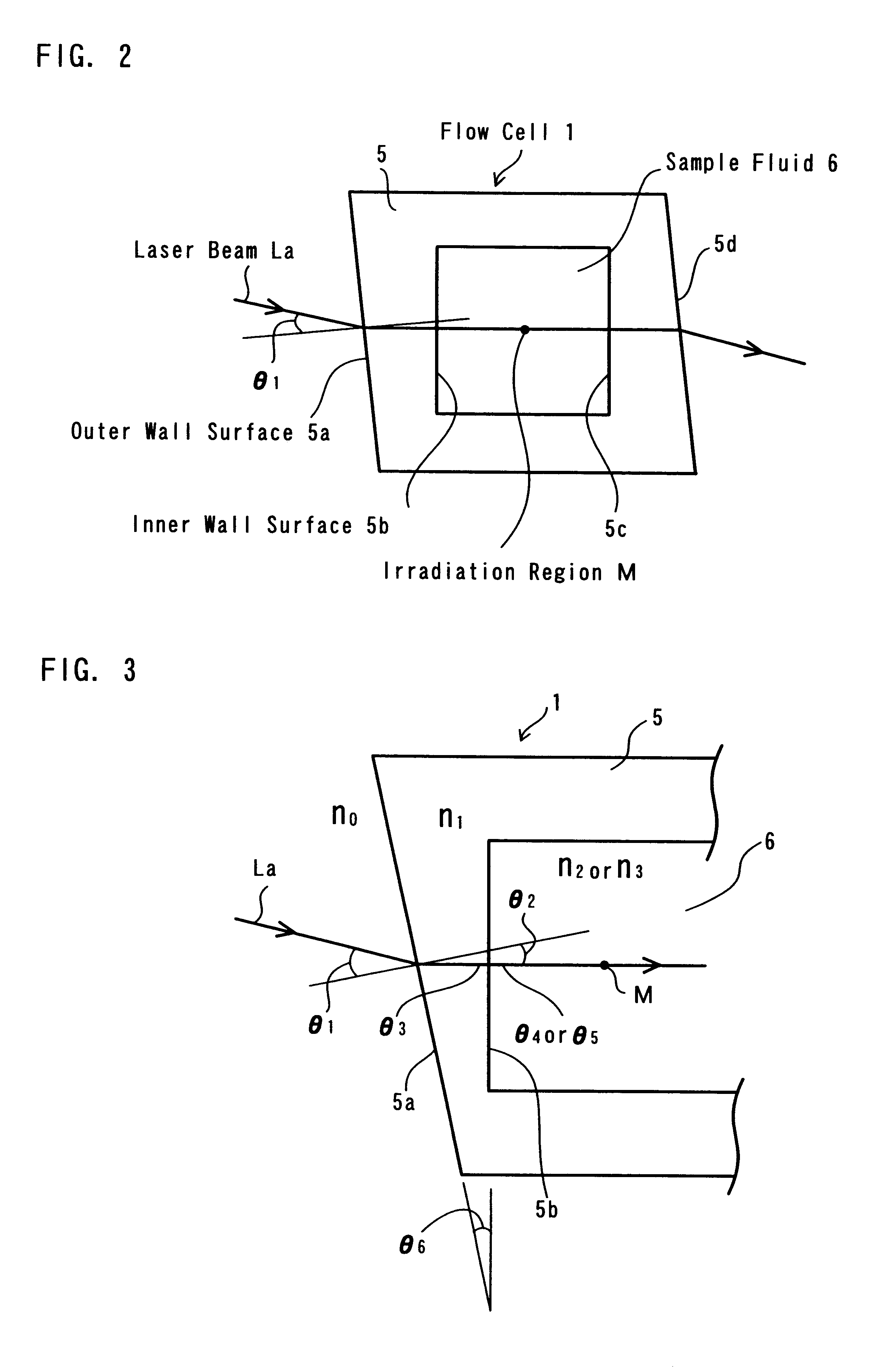
Also, the flow cell, according to the present invention, is constructed of a wall portion 5 having a quadrilateral shape in the cross-section thereof, as shown in FIG. 2. The cross-section of an inner periphery thereof is square in shape while the cross-section of an outside thereof is a parallelogram in shape.

Accordingly, an outer wall surface 5a upon which a laser beam La is incident and an inner wall surface 5b from which the laser beam La exits are not parallel each other, but instead the outer wall surface 5a defines a predetermined angle (inclination) with respect to the inner wall surface 5b. In the same manner, an opposite inner wall surface 5c upon which the laser beam La is incident and an outer wall surface 5d from which the laser beam La exits outside are not parallel each other, but instead the outer wall surface 5d defines a predetermined angle (inclination) with respect to the inner wall surface 5c.

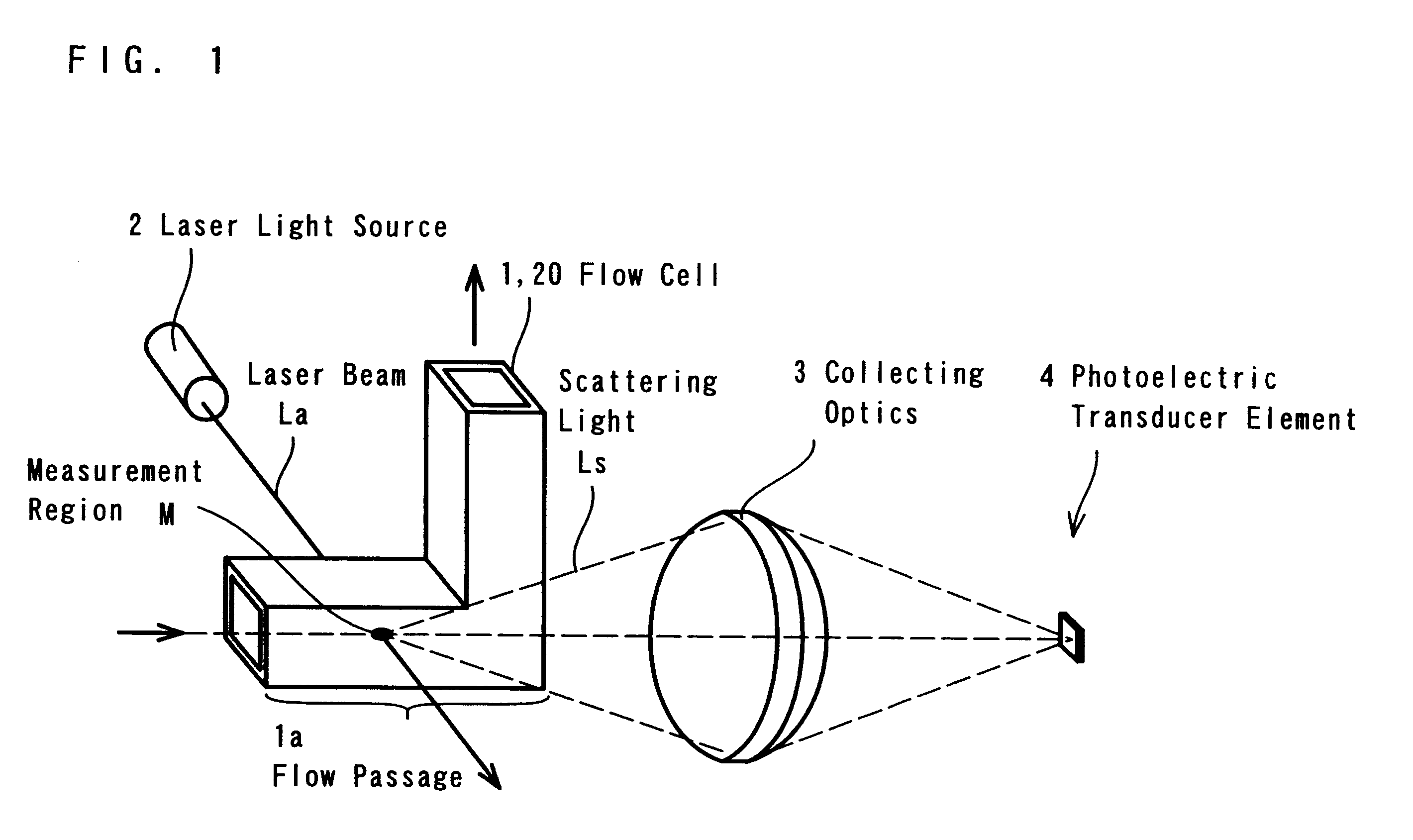
Again referring to FIG. 1, a straight flow passage 1a of a predetermin...

third embodiment

As the third embodiment shown in FIG. 5, it is also possible to make one small portion of each of the outer wall surfaces 15a and 15d have the necessary shape not parallel to the inner wall surfaces 15b, 15c, respectively , through which the laser beam La passes, by attaching or bonding members 21 with non-parallel outer surfaces and made of the same material as the flow cell to the outer wall surfaces 15a and 15d respectively.

In the first embodiment of the flow cell according to the present invention, as shown in the FIG. 2, regarding the wall portion 5 of the flow cell 1, an angle defined between the outer wall surface 5a and the inner wall surface 5b is made equal to an angle defined between the outer wall surface 5d and the inner wall surface 5c in symmetry, thereby preventing the laser beam La from turning reflecting or back along the light path by reflecting on the boundary surface between the outer wall surface 5d and air.

By the way, the form of the angle between the inner wa...

fourth embodiment

Next, a flow cell 30, according to the present invention, has a wall portion 5 of a quadrilateral shape in the cross-section thereof, as shown in FIG. 6. The shapes in the cross-section of an inner periphery and an outer periphery thereof are both trapezoidal.

The outer wall surface 5a upon which the laser beam La is incident and the inner wall surface 5b from which the laser beam La exits are not parallel each other. The outer wall surface 5a is formed to define a predetermined angle (i.e., inclination) with respect to the inner wall surface 5b.

Further, the inner wall surface 5b from which the laser beam 1a exits and the inner wall surface 5c upon which the laser beam La is incident are not parallel each other. The inner wall surface 5c is formed to define a predetermined angle (i.e., inclination) with respect to the inner wall surface 5b.

As shown in the FIG. 6, the laser beam La is incident upon the boundary surface between air and the outer wall surface 5a at an incident angle .th...


PUM


Abstract

A flow cell for obtaining information on particles suspended in sample fluid, wherein an irradiation region M is defined in the flow cell for functioning as a particle detection portion to be irradiated with a laser beam La, and a wall portion of the flow cell is so adapted and arranged that the laser beam La becomes incident upon an outer wall surface of the flow cell 1 at a predetermined angle theta1 (theta1<> 0°) and exits from an inner wall surface 5b of the flow cell 1 into the sample fluid 6 at a refraction angle 0°.Further the wall portion 5 of the flow cell 1 is so arranged that the laser beam La becomes incident upon a boundary surface between the sample fluid and the opposite inner wall surface of the flow cell 1 at a predetermined incident angle alpha (alpha<> 0°) after being incident upon the sample fluid and passing through the irradiation region M.

Description

1. Field of the InventionThe present invention relates to a flow cell for forming an irradiation region therein, as a particle detector portion, and to a particle measurement apparatus for obtaining particle information, including a diameter of particles and so on, which are suspended in sample fluid passing through the irradiation region by using the flow cell.2. Description of Relevent ArtAs shown in FIG. 8, a conventional flow cell 100 is made of a transparent material, and is constructed to have a straight flow path or passage of a predetermined length, having a square cross-section thereof. And, an outer wall surface 101a and an inner wall surface 101b of a wall portion 101, constructing the flow cell 100 through which a laser beam La passes, are formed to be parallel each other.Also, as shown in FIG. 9 when the laser beam La from a laser light source is irradiated upon the flow cell 100, the laser beam La is incident upon a boundary surface between air and the outer wall surfa...

Claims


Application Information

Patent Timeline
IPC IPC(8): G01N15/02
CPCG01N15/0205
Inventor MATSUDA, TOMONOBU
Owner RION COMPANY
Why Eureka
Try Eureka