
Transflective liquid crystal display device and method of manufacturing the same

a liquid crystal display and reflector technology, applied in static indicating devices, instruments, non-linear optics, etc., can solve the problems of reflective lcd devices, battery cannot be used for a long time, and the backlight device's electric power consumption increases

Inactive Publication Date: 2002-10-15
LG DISPLAY CO LTD
View PDF6 Cites 137 Cited by
  • Summary
  • Abstract
  • Description
  • Claims
  • Application Information

AI Technical Summary

Problems solved by technology

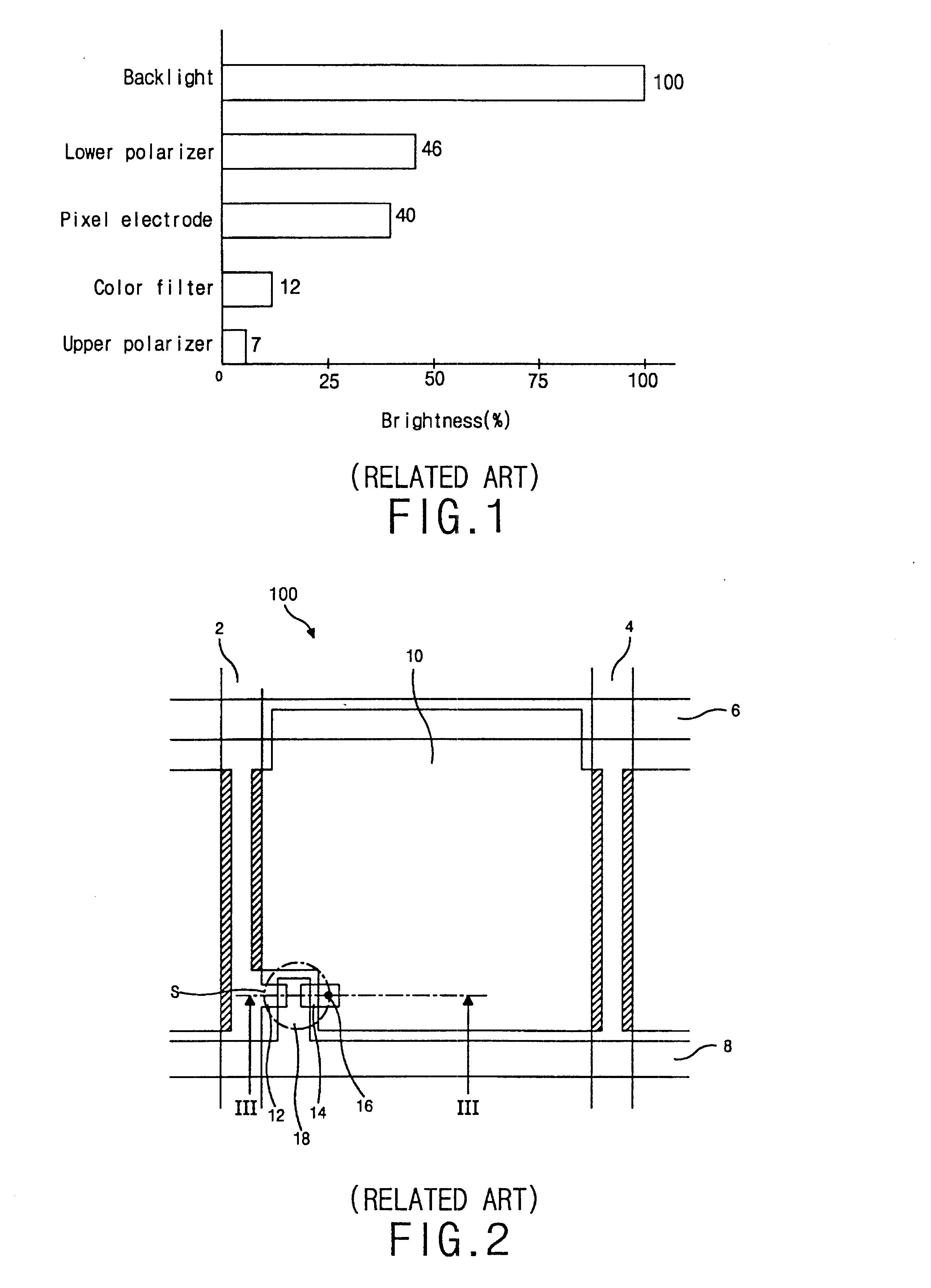
For such a reason, the transmissive LCD device requires a high brightness of the back light device, and thus an electric power consumption by the backlight device increases.
In order to supply a sufficient power to the backlight device, a relatively heavy battery is employed, however, there still exists a problem that the battery can not be used for a long time.
By the way, the reflective LCD device has a problem that it is affected by its surroundings.
Therefore, the reflective LCD device can not be used at night without ambient light.

Method used


Image

  • Transflective liquid crystal display device and method of manufacturing the same
  • Transflective liquid crystal display device and method of manufacturing the same
  • Transflective liquid crystal display device and method of manufacturing the same

Examples


Embodiment Construction

Reference will now be made in detail to the preferred embodiment of the present invention, example of which is illustrated in the accompanying drawings.

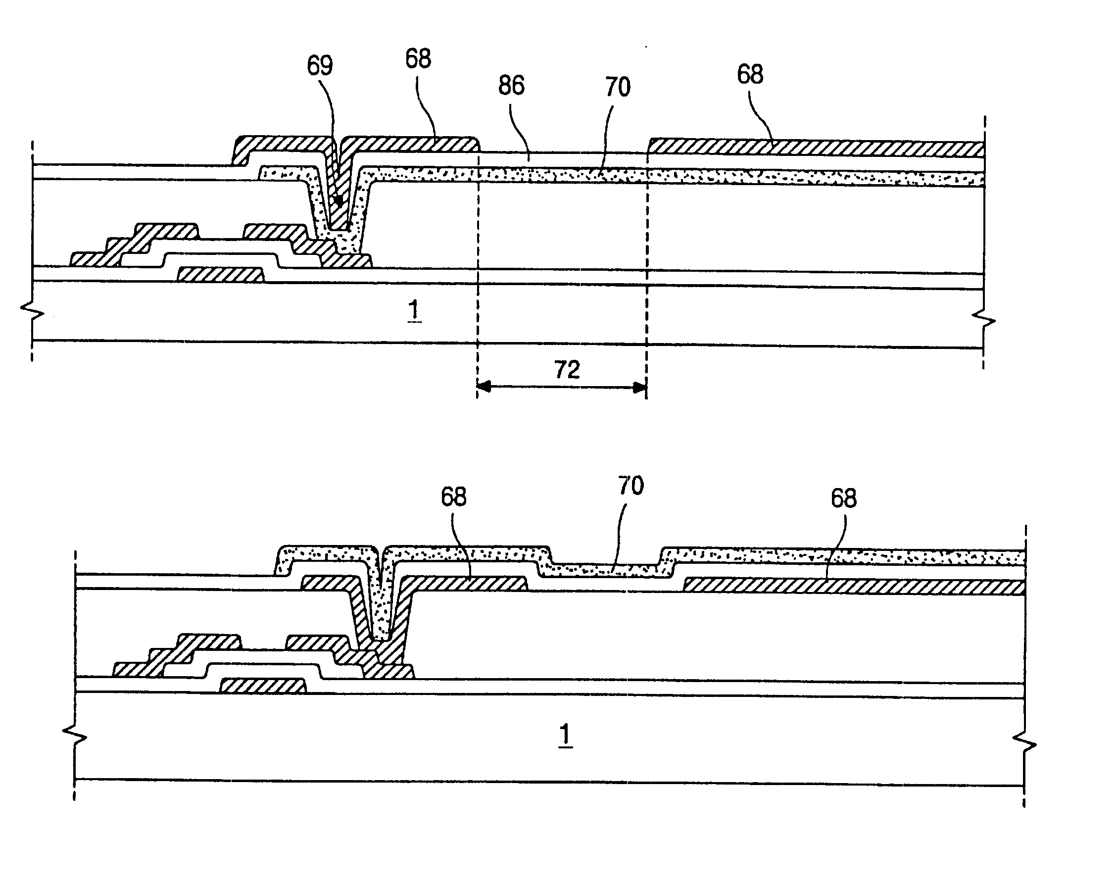
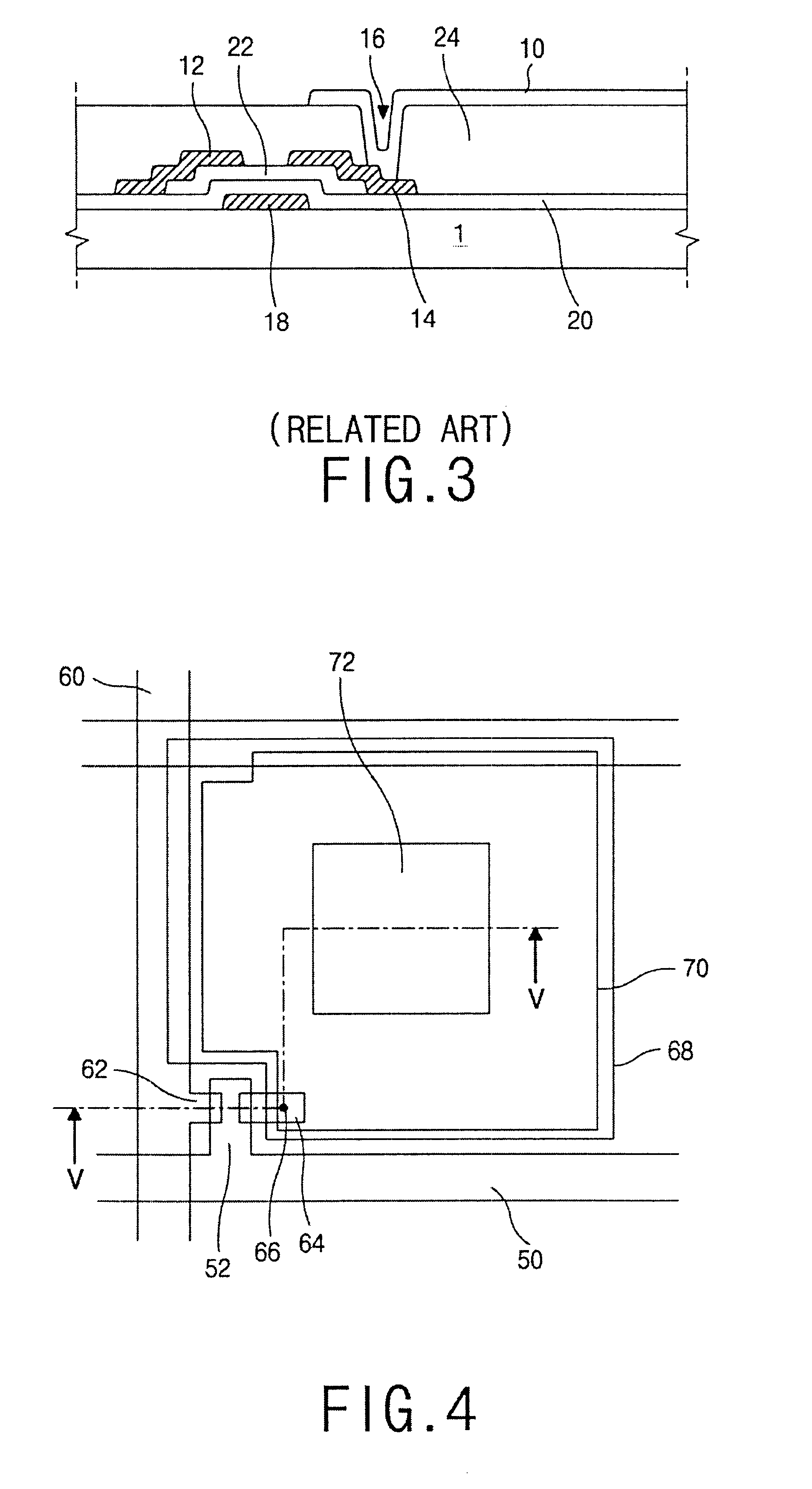
FIG. 4 is a plan view illustrating an array substrate of a transflective liquid crystal display (LCD) device according to a preferred embodiment of the present invention. As shown in FIG. 4, the array substrate includes gate line 50 arranged in a transverse direction, data line 60 arranged in a longitudinal direction perpendicular to the gate line 50, and a thin film transistor (TFT) arranged near the cross portion of the gate and data lines 50 and 60. The TFT has a gate electrode 52, a source electrode 62 and a drain electrode 64. The gate electrode 52 extends from the gate line 50, and the source electrode 62 extends from the data line 60. The array substrate further includes a reflective electrode 68 and a pixel electrode 70, which are formed on a region defined by the gate and data lines S0 and 60. The reflective electrode 68 and...


PUM

PropertyMeasurementUnit
transmittanceaaaaaaaaaa

Abstract

The present invention discloses A transflective liquid crystal display device including a first substrate having a color filter; a second substrate having: a)a gate electrode formed on the second substrate; b) a first insulating layer formed on the exposed surface of the second substrate while covering the gate electrode; c) a semiconductor layer formed on the first insulating layer and over the gate electrode; d)a source electrode overlapping one end portion of the semiconductor layer; e) a drain electrode overlapping the other end portion of the semiconductor layer and spaced apart from the source electrode; f) a second insulating layer formed on the exposed surface of the first insulating layer while covering the source and drain electrode, having a first contact hole formed on a portion of the drain electrode; g) a pixel electrode formed on the second insulating layer and electrically connected with the drain electrode through the first contact hole; h) a third insulating layer on the pixel electrode and having a second contact hole over the first contact hole; and i) a reflective electrode formed on the third insulating layer and having a light transmitting hole and electrically connected with the pixel electrode through the second contact hole, the light transmitting hole transmitting light and covered by the pixel electrode; a liquid crystal display layer interposed between the first and second substrates; and a back light device for supplying light and located under the second substrate.

Description

1. Field of the InventionThe present invention relates to a liquid crystal display (LCD) device, and more particularly, to a transfiective LCD device and a method of manufacturing the same.2. Description of Related ArtIn general, LCDs are divided into transmissive LCD devices and reflective LCD devices according to whether the display uses an internal or an outer light source.A typical transmissive LCD device comprises a liquid crystal panel and a back light device. The liquid crystal panel includes upper and lower substrates with a liquid crystal layer interposed therebetween. The upper substrate has a color filter, and the lower substrate has a thin film transistor (TFT) as a switching element. An upper polarizer is arranged on the upper substrate of the liquid crystal panel, and a lower polarizer is arranged between the lower substrate of the liquid crystal panel and the backlight device.At this time, the two polarizers have a transmittance of 45%, the two substrates have a trans...

Claims


Application Information

Patent Timeline
Patent Type & Authority Patents(United States)
IPC IPC(8): G02F1/1335G02F1/13G02F1/1362G02F1/1343
CPCG02F1/133555G02F1/136227G02F1/1343
Inventor PARK, SUNG-ILCHUNG, JAE-YOUNG
Owner LG DISPLAY CO LTD
Learn More