
Security sensor having disturbance detecting capability

a technology of security sensors and detection capabilities, applied in the field of security sensors of types, can solve the problems of reducing the amount of light reflected from the obstacle so much, and the detection of the increment of light reflected from the obstacle is difficult to achieve, and the detection of disturbance detectors may fail to achiev

Inactive Publication Date: 2002-10-22
OPTEX CO LTD
View PDF13 Cites 108 Cited by
  • Summary
  • Abstract
  • Description
  • Claims
  • Application Information

AI Technical Summary

Benefits of technology

In a preferred embodiment of the present invention, the use is made of a light guide member for guiding the disturbance detecting beam reflected from the obstacle towards the light receiving element. Since this light guide member guides the disturbance detecting beams, which has been reflected from the obstacle, so as to travel towards the light receiving element, the freedom of positioning the light receiving element can increase.
Also, preferably, the light guide member is positioned at a location offset from an incident area aligned with the infrared sensor element. Positioning of the light guide member in this manner will not cause the presence of the light guide member to reduce the disturbance detecting capability of the security sensor.
In a preferred embodiment of the present invention, the infrared sensor element and the light projecting elements are mounted on a printed circuit board. This enables a wiring circuit to be simplified.
Again in a preferred embodiment of the present invention, the carrier body includes a base for supporting the infrared sensor element, the light projecting element and the light receiving element mounted thereon, and a casing fitted to the base; wherein a lens which is the incident side enclosure is fitted to the casing. The carrier body and the lens cooperate to enclose the infrared sensor element, the light projecting element and the light receiving element while the projections are formed on a center portion of the lens. According to this design, since the projections are positioned where the obstacle is likely to be applied, any act of fooling or tampering with the lens of the security sensor can effectively be prevented.
Yet, the carrier body may alternatively include a base for supporting the infrared sensor element, the light projecting element and the light receiving element mounted thereon, and a cover which is the incident side enclosure and which is fitted to the base so as to enclose the infrared sensor element, the light projecting element and the light receiving element, and wherein the projections are formed on a portion of the cover encompassed in and within the detection area. According to this design, any act of fooling or tampering with the cover of the security sensor with no lens can effectively be prevented.

Problems solved by technology

It has often been experienced that the intruder detecting system is tampered with an obstacle such as, for example, a transparent sticker or label of a kind capable of transmitting therethrough rays of light ranging from a visible wavelength region to a near infrared wavelength region, but intercepting far infrared rays of light, so that the intruder detecting system may be fooled enough to allow an intruder to trespass on the detection area monitored by the passive-type infrared sensor element.
It has, however, been found that with the disturbance detector used in the prior art security sensor, detection of the increment of the light reflected from the obstacle is difficult to achieve where the amount of the obstacle detecting light reflected from the obstacle is insufficiently small relative to the standard amount of the light incident on the light receiving element because the obstacle detecting light reflected from the inner surface of the lens may travel astray.
In particular, in the event that the obstacle such as, for example, a transparent sticker of a kind capable of intercepting far infrared rays of light, but transmitting therethrough the obstacle detecting light of a wavelength ranging from a near infrared wavelength region to a visible wavelength region is tightly affixed to a front surface of the lens, the lens and the transparent sticker are integrated together and, hence, the amount of light reflected from the obstacle decreases so extremely that the disturbance detector may fail to detect it.
Moreover, since the transparent sticker is virtually indiscernilde with eyes, the presence or absence of the obstacle on the lens is not easy to detect with eyes.
However, the former does not only require the disturbance detector to be activated at all times, but also is susceptible to an erroneous detection resulting from an erroneous operation of the disturbance detector.
On the other hand, the latter may often result in an erroneous detection even when small insects traverse.
Also, even though a small obstacle such as a fly or an insect perches temporarily on the outer surface of the incident side enclosure, and since the amount of the light reflected from such small obstacle is small, there is no possibility of the security sensor functioning erroneously.

Method used


Image

  • Security sensor having disturbance detecting capability
  • Security sensor having disturbance detecting capability
  • Security sensor having disturbance detecting capability

Examples


Embodiment Construction

Hereinafter, preferred embodiments of the present invention will be described with reference to the accompanying drawings.

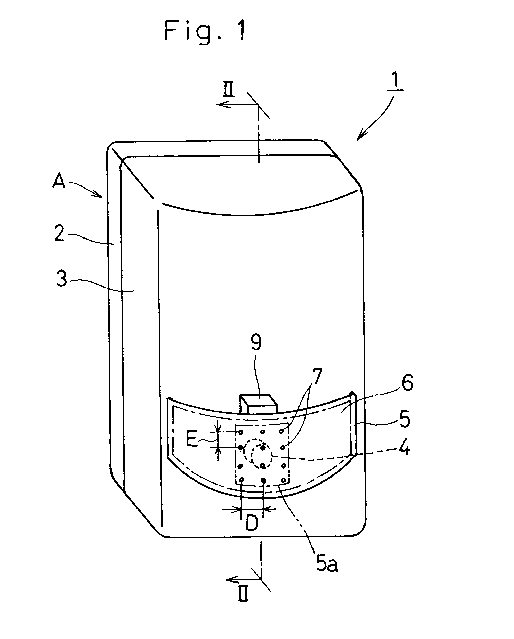
FIG. 1 illustrates a perspective view of a security sensor according to a first preferred embodiment of the present invention. This security sensor 1 includes a generally rectangular box-like carrier body A made up of a generally rectangular base 2 adapted to be fitted to a support surface such as, for example, a ceiling or a wall, and a cap-like cover casing 3 fitted to the base 2 for covering a front surface region of the base 2, and a pyroelectric element which is a passive-type far infrared sensing element and which is accommodated within the carrier body A. The casing 3 is detachably secured to the base 2 by means of a plurality of fitting screws (not shown).

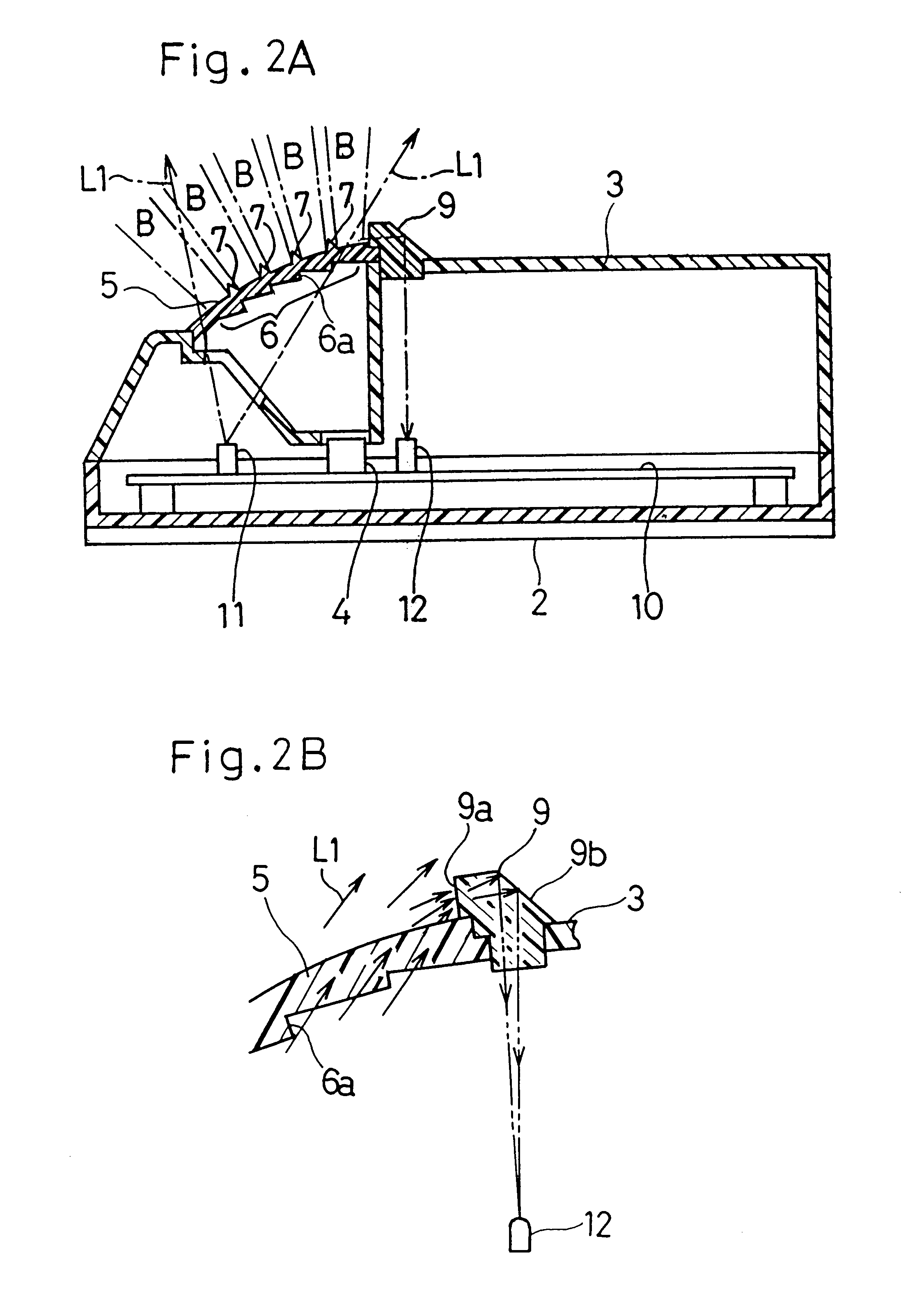
As shown in FIG. 2A, the casing 3 made up of top and side walls has a generally rectangular opening in which a lens 5 serving as an incident side enclosure is fitted. This lens 5 concurrently serves as a...


PUM


Abstract

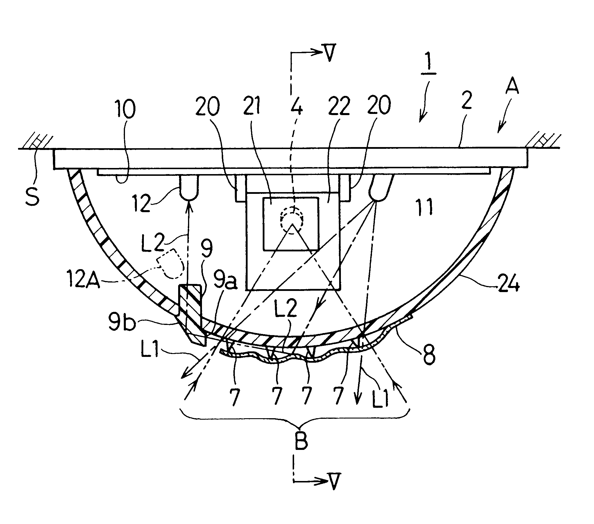
A security sensor 1 having a disturbance detecting capability capable of detecting the presence of an obstacle 8 purposefully applied to the sensor 1 in an attempt to fool or tamper the sensor 1 includes a carrier body A having an infrared sensor element 4, an incident side enclosure 5, such as a lens defining a detection area B, mounted on the carrier body A, a light projecting element 11 for projecting a disturbance detecting beam L1 from inside of the incident side enclosure 5 towards the incident side enclosure 5, a light receiving element 12 for receiving the disturbance detecting beam L1 reflected from the incident side enclosure 5, and a detecting circuit 15 for detecting a presence or absence of the obstacle 8 on the incident side enclosure 5, based on an amount of light received by the light receiving element 12. A multiplicity of projections 7 are formed on an outer surface of the incident side enclosure 5 so as to define a multiplicity of gaps between the obstacle 8 and the outer surface of the incident side enclosure 5, when the obstacle 8 is applied to the outer surface of the incident side enclosure 5.

Description

1. Field of the InventionThe present invention generally relates to a security sensor of a type utilizing a passive-type infrared sensor element and, more particularly, to the security sensor of a type having a disturbance detecting capability for detecting the presence or absence of an obstacle such as, for example, a sticker or label affixed to the sensor casing to disable the security sensor.2. Description of the Prior ArtAn intruder detecting system utilizing the security sensor of the type referred to above is so designed and so configured as to detect an intruder within a detection area or a detection area in reference to the difference between the temperature of a human body and the ambient temperature when the passive-type infrared sensor element receives far infrared rays of light emitted from the human body within the detection area.It has often been experienced that the intruder detecting system is tampered with an obstacle such as, for example, a transparent sticker or l...

Claims


Application Information

Patent Timeline
Patent Type & Authority Patents(United States)
IPC IPC(8): G08B29/00G08B29/04G08B29/18G01J1/02G01V8/10G08B13/193
CPCG08B29/046
Inventor TOMOOKA, HIROYUKI
Owner OPTEX CO LTD
Learn More