Potentiometric position sensors

a technology of position sensors and potentiometers, applied in the direction of resistors, instruments, converting sensor output, etc., can solve the problem of not being able to easily pull apart, and achieve the effect of simple and easy handling and installation

Inactive Publication Date: 2002-11-05
A B ELECTRONICS
View PDF8 Cites 4 Cited by
  • Summary
  • Abstract
  • Description
  • Claims
  • Application Information

AI Technical Summary

Benefits of technology

It is the object of the invention to provide a new approach to potentiometric sensor design which avoids the disadvantages noted above, and to enable the supply of products to manufacturers which may be simply and easily handled and installed in any item in which it is desired to determine change in the angular position of two relatively movable parts.

Problems solved by technology

The mutually engaging formations may be so configured that the members clip together easily, but cannot be easily pulled apart.

Method used


Image

  • Potentiometric position sensors
  • Potentiometric position sensors
  • Potentiometric position sensors

Examples


Embodiment Construction

.

The invention is further explained and illustrated by way of example with reference to the accompanying drawings in which:

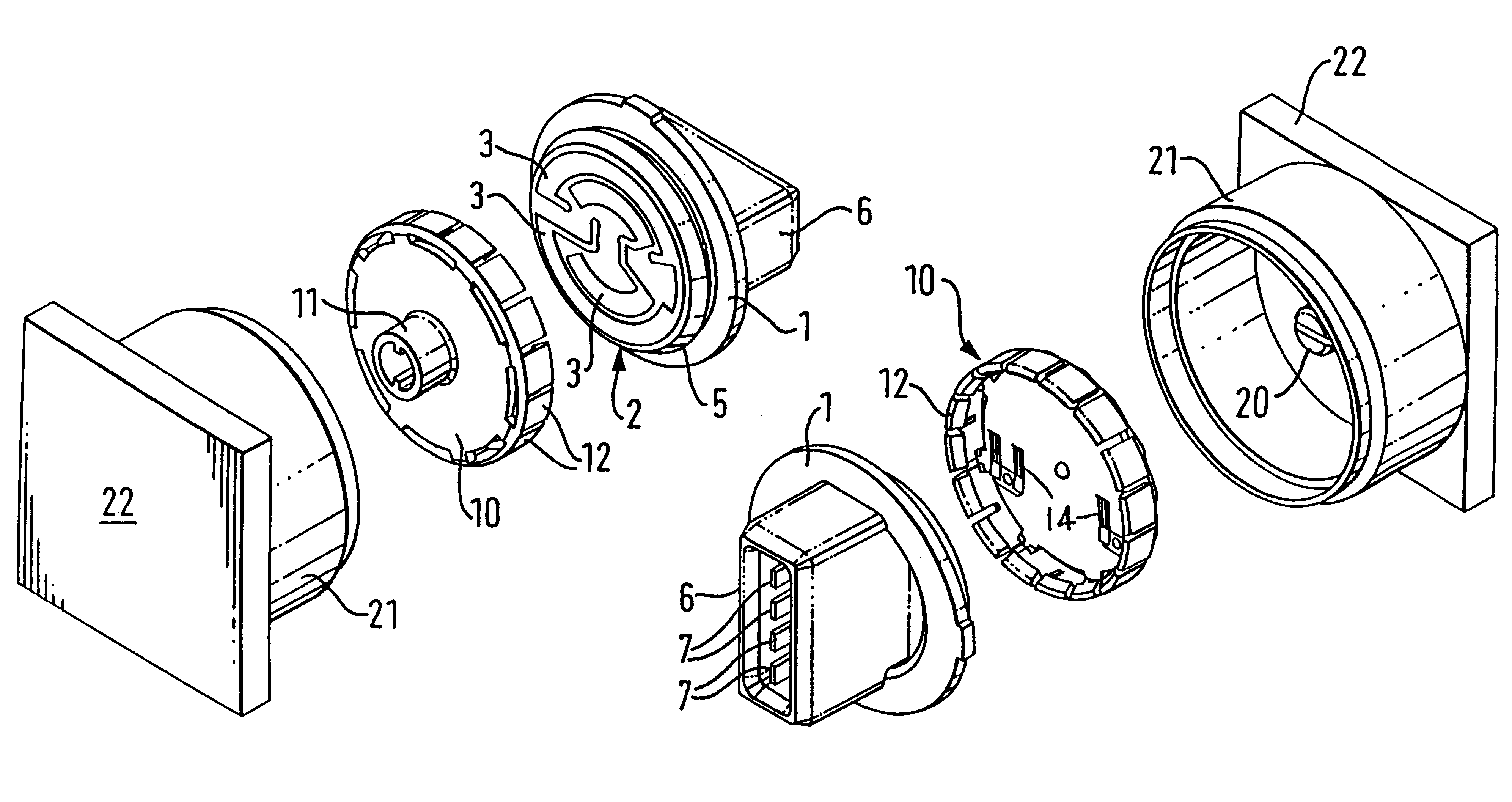
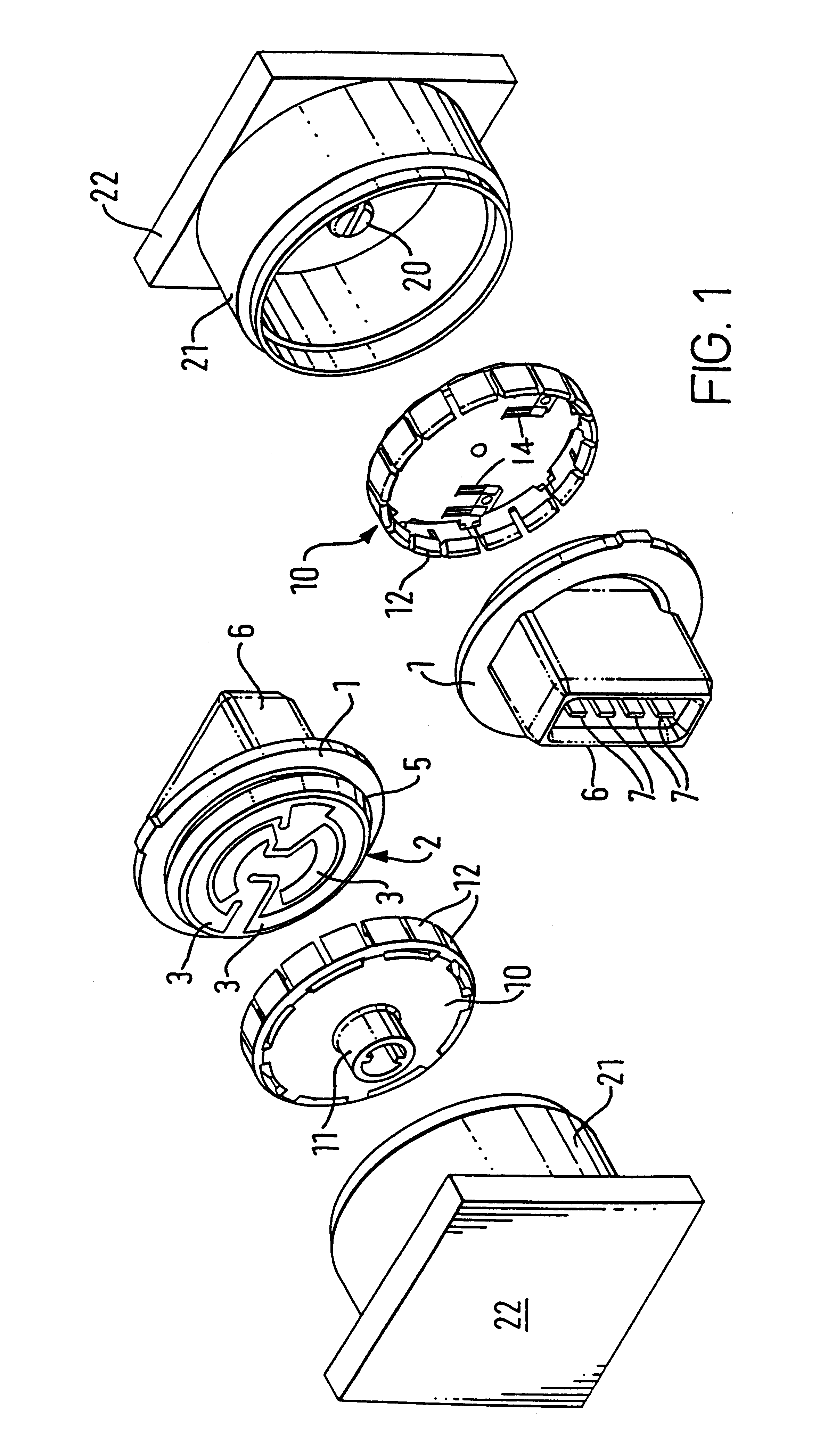
FIG. 1 shows an exploded view and from two different directions a rotary potentiometer sensor assembly suitable for fitting to a throttle body, for example forming part of a motor vehicle,

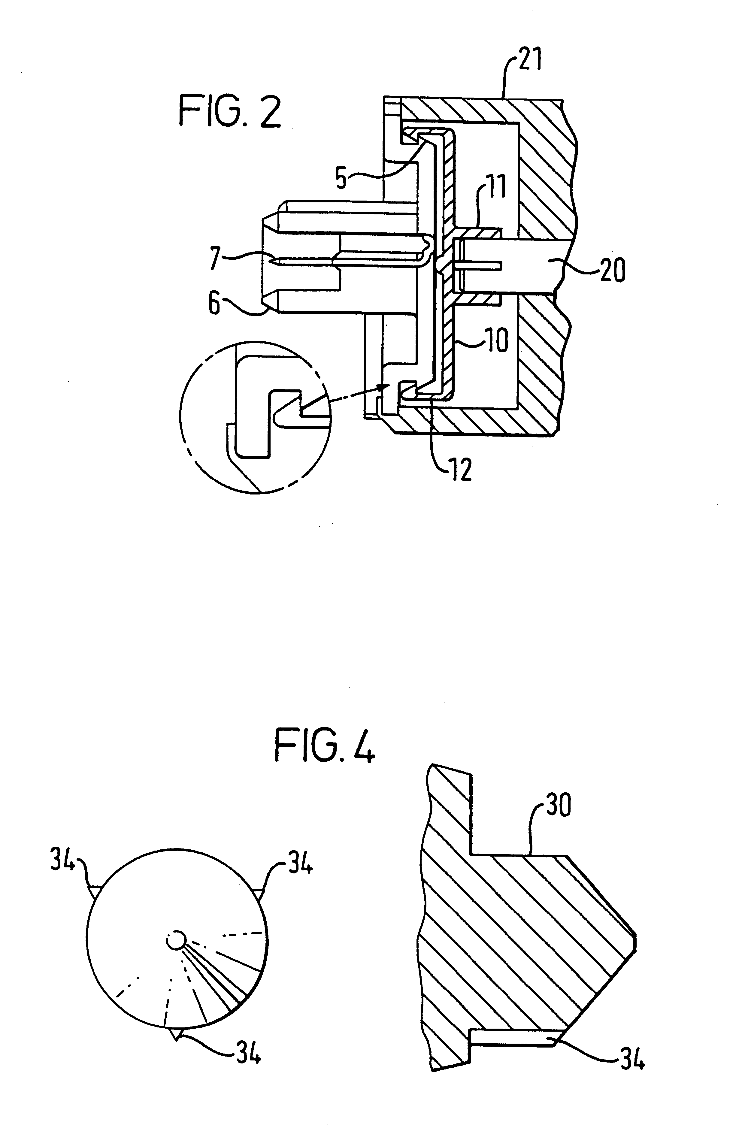
FIG. 2 is an axial section through the assembled sensor arrangement of FIG. 1,

FIG. 3 is an axial section of alternative rotary and insulative substrats members, and showing a typical printed track arrangement, and

FIG. 4 is a section through a further alternative rotary and insulative substrate member again showing the track arrangement and with a detail of a self-centring pin.

Referring first to FIG. 1, this shows an exploded view from two different directions of a rotary potentiometer sensor structure in accordance with the invention. An insulating substrate member 1 moulded from a suitable plastics material includes on one side a circular face 2 on which are a number of pre-pr...


PUM


Abstract

By using a two-part assembly of a rotary member (10) bearing one or more wipers (14) clipped on to a substrate member (1) bearing one or more tracks (3), subassemblies may be supplied which can be used by manufacturers of articles (20,21,22) in which it is desired to sense the angular position of one member (20) relative to another (22), but which are easy to install and reliable in use. The assembly provides substantial savings in terms of the number of individual components used, thus reducing manufacturing and assembly costs. Manufacturing costs may also be reduced by using track material as a bearing material, as both track and bearing may be applied simultaneously, e.g. by screen printing.

Description

This invention relates to potentiometric position sensors.BACKGROUND TO THE INVENTIONPotentiometric position sensors find widespread application in industry in the measurement of angle or linear position. By fixing one part of a potentiometer to one component and another to another component, relative movement between the components causes a change in the electrical potential sensed by a contact wiper which moves along the track of resistive material. This change may be sensed by suitable circuitry, and used to provide an indication of angle or linear position.Potentiometers have been manufactured for many decades as self-standing components, usually consisting of a casing within which is an insulating substrate on which a resistive track is present. A wiper is held resiliently against the track and the position of the wiper may be changed by rotation of a spindle or linear movement of a sliding member. Conventionally, the spindle or sliding member has to be attached to a component ...

Claims


Application Information

Patent Timeline
Patent Type & Authority Patents(United States)
IPC IPC(8): G01D5/165G01D5/12H01C10/32H01C10/00
CPCG01D5/1655H01C10/32
Inventor DIETRICH, FRANK HERMANN
Owner A B ELECTRONICS
Why Eureka
Try Eureka