

Disk drive with unbalance correcting mechanism
a technology of unbalance correcting and disk drive, applied in the field of disk drive, can solve the problems of increasing cost, changing the correcting function, and obtaining stable unbalance correcting function, so as to prevent immobility and straying balls, reduce the time of running-in operation, and reduce the cost
Inactive Publication Date: 2002-11-05
HITACHI LTD
View PDF3 Cites 40 Cited by
- Summary
- Abstract
- Description
- Claims
- Application Information
AI Technical Summary
Benefits of technology
An object of the present invention is to provide a disk drive, which solves the above problems and which can reduce time for running-in operation to lower cost and prevent immobility and straying of balls.
Problems solved by technology
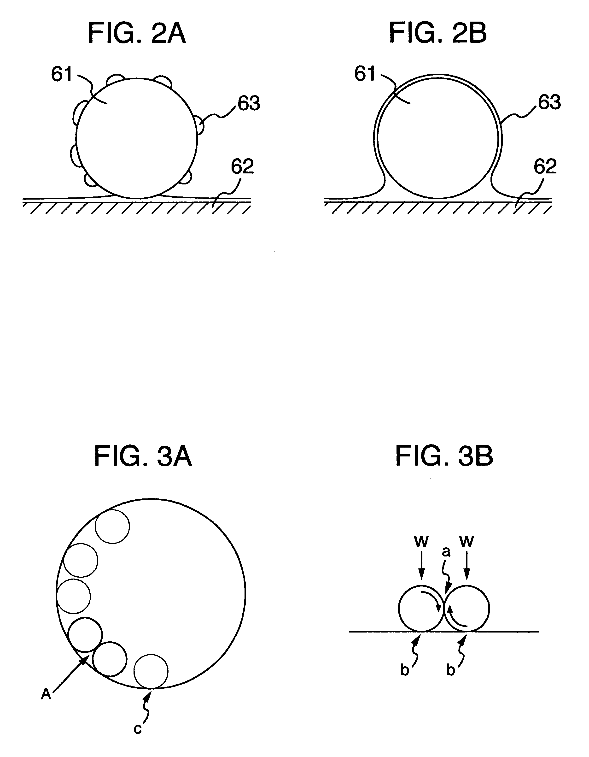
In such an unbalance correcting mechanism, there is a fear that the balls and the rolling groove slidingly contact with each other as a disk drive is driven, and so fitting of contact portions proceeds to cause a change in correcting function.
In approximately 200 hours of preliminary operation, fitting of contact portions and diffusion of a lubricant are completed with the result that a stable unbalance correcting function can be obtained.
Time required for the running-in operation is a cause for an increase in cost, and so it is essential to shorten such time as much as possible.
These particles may get filled between the balls and the rolling groove to obstruct smooth movements of the correcting member and further make the balls immovable, which adversely affects reliability of the disk drive.
When an amount of the lubricating oil is too much, however, restraining forces on the balls and the rolling groove may become excessively great to cause immobility of the balls. conversely, when an amount of the lubricating oil is too little, restraining forces on the balls and the rolling groove may become excessively small to cause the balls to stray, so that the balls fail to stop relative to the rolling groove at the unbalance correcting position.
It is difficult to adjust friction between the balls. and the ring groove to a level not too large or too small.
So, such adjustment imposes a problem.
Also, it is another problem to adjust the hardness of the hard film formed in the ring groove to an optimum level.
H11-156243 also imposes a problem in a high-density storage apparatus such as disk drives.
Also, rubber having a thickness on the order of micron is liable to generate contamination due to wear.
When ethylene glycol is added, it is problematic to optimize an amount added.
Method used
View moreImage
Smart ImageViewing Examples

Examples
embodiment 1
(Embodiment 1)
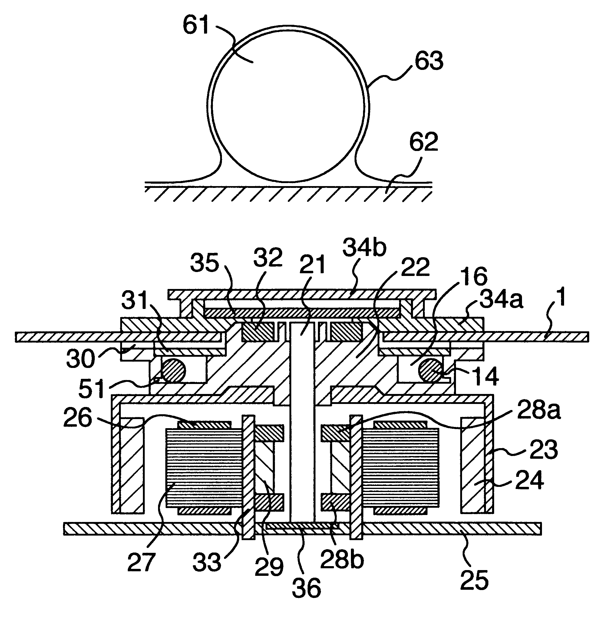
12 balls having been subjected to surface treatment with heptadecafluorodecyltrimethoxysilane and a turntable applied with 5 .mu.m of KANIBORON TM plating (Ni--P--B) were used to assemble a CD-ROM unit mechanism with 1 .mu.l of ester oil injected into a rolling groove.
Login to View More PUM
| Property | Measurement | Unit |
|---|---|---|
| surface tension | aaaaa | aaaaa |
| contact angle | aaaaa | aaaaa |
| temperature | aaaaa | aaaaa |
Abstract
A disk drive is realized, which omits running-in for stabilizing a change in a correcting function produced by sliding between balls and a rolling groove in an unbalance correcting mechanism, and prevents immobility and straying of balls, and which comprises a unit mechanism assembled by using 12 balls subjected to surface treatment with heptadecafluorodecyltrimethoxysilane and a turntable plated with a chemical nickel plating containing phosphorus and boron to have a thickness of 5 mum and by injecting 1 microliter of ester oil into the rolling groove, and further comprises a recess formed in a sidewall of the rolling groove of the unbalance correcting mechanism to prolong the service life of the correcting function.
Description
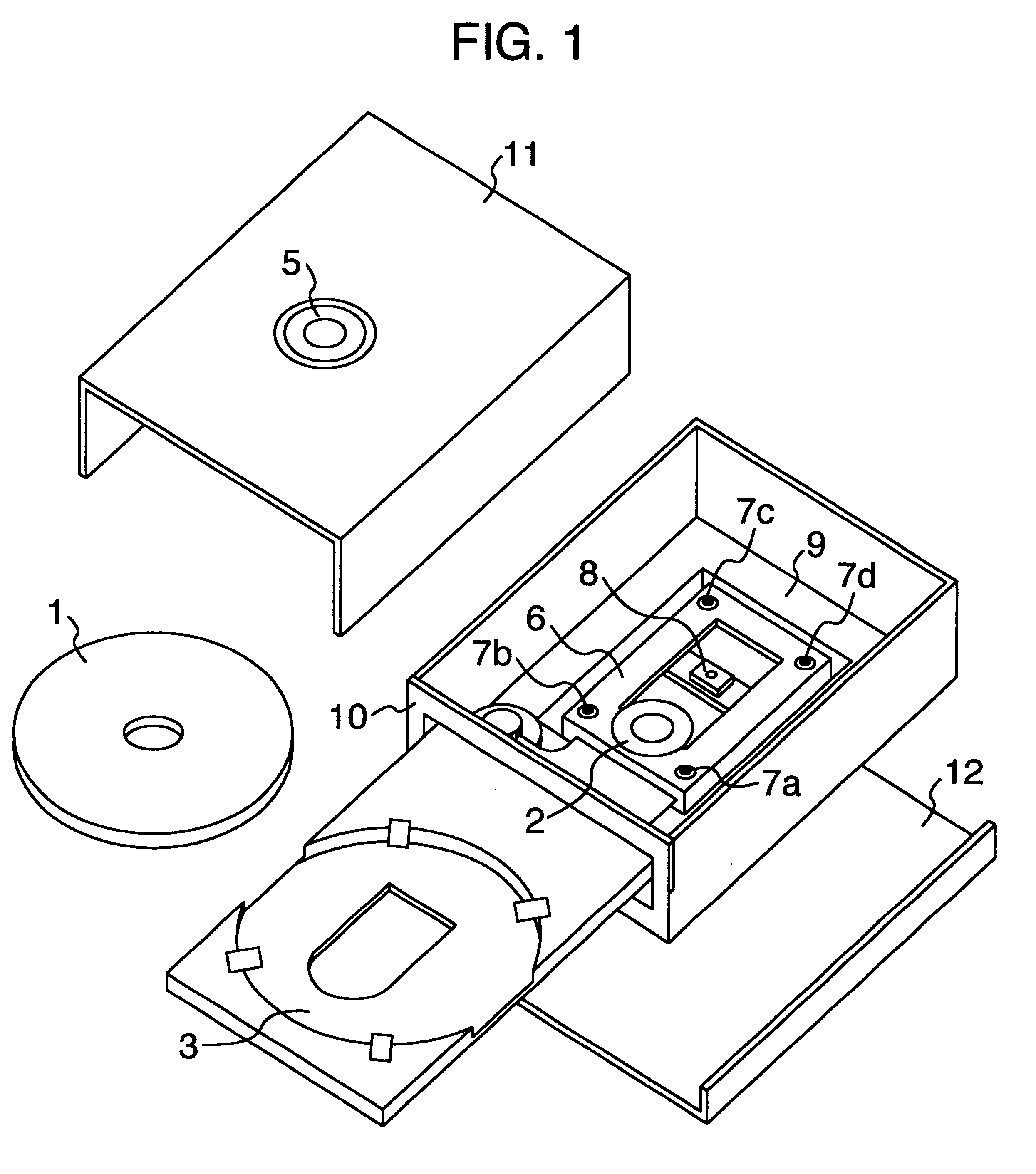
The invention relates to an unbalance correcting mechanism having rollable balls and a rolling groove to correct unbalance generating in a rotating device, and more specifically to a disk drive, such as CD-ROM and DVD-ROM drives, which reproduce information, or DVD-RAM, MO and removable HD drives, which write and read information, for rotating a disk-shaped, removable recording medium at high speed.Japanese Patent Gazette No. 2,824,250 describes a balancer for correcting unbalance of a disk drive. The balancer comprises a hollow annular portion formed integral with a rotor and balancing members (spherical bodies) movable in the hollow annular portion. Japanese Patent Unexamined Publication No. H10-92094 describes a disk type storage device comprising at least one balance correcting weight freely movable on a path having a center of rotation, which coincides with that of a disk to automatically correct unbalance of the disk.Japanese Patent Unexamined Publication No. H11-154371 descri...
Claims
Login to View More Application Information
Patent Timeline
 Patent Type & AuthorityPatents(United States)
IPC IPC(8): G11B33/08G11B17/028G11B17/022F16F15/32G11B19/20
CPCG11B33/08G11B17/0284
InventorYOSHIMURA, YASUHIROENDO, YOSHISHIGENII, KATSUTOSHISATOU, YOSHIHIROYAMAUCHI, YOSHIAKIKUMASAKA, NORIYUKIOYAMA, KAZUTOMIKI, HISAHIROHIRATA, TOMOKI
OwnerHITACHI LTD