
Verification of active nodes in an open network

a technology of active nodes and open networks, applied in data switching networks, frequency-division multiplexes, instruments, etc., can solve problems such as avalanche-type failure, no guarantee that all relevant nodes have received the message, and inability to verify broadcast protocols

Inactive Publication Date: 2002-11-12
KONINKLIJKE PHILIPS ELECTRONICS NV
View PDF5 Cites 104 Cited by
  • Summary
  • Abstract
  • Description
  • Claims
  • Application Information

AI Technical Summary

Benefits of technology

There is a need for a method to identify active, inactive and / or new nodes on the network without using a broadcast protocol with its numerous deficiencies. It is therefore an object of the invention to provide a network and a method for enabling operation or configuration of a network without having to rely too heavily on the conventional broadcast protocols mentioned above.
To this end, the invention provides a linked-node network including a network protocol that is implemented on each node of the network. The protocol is designed to form the network into a logically linked configuration of nodes such as a logical ring, chain or equivalent. The protocol includes at least one node address, a polling timer, a node counter, polling, healing and dummy tokens / messages, routines for sending and receiving tokens, for monitoring network integrity (testing for time-outs without token return), for adding or removing nodes, for healing or repairing breaks in the network when active nodes go inactive, for defragmenting a network, for fragmenting a network from a super network and for facilitating node resource sharing. The protocol can operate under natural node-timer staggering but controlled, even node-timer staggering is preferred.
The invention further provides a method for adjusting the timer values at each node to create an evenly staggered network. The method starts with a transit time set by the network system designer and adjusts the timers so that the polling token resides at each node for a time of about one no the network transit time, or more accurately, one no the network transit time minus the inter-node transit time, wherein n is the number of active nodes. Because the protocol is designed to operate in the background, this protocol feature ensures that the timers at each node have sufficiently long ranges so that token processing is able to occur and that other network processing such as add / remove node processes can be initiated. The method also includes start-up routines that start the timers off at some estimated timer setting The setting is then dynamically adjusted using an accumulated time and incremental time so that as token propagation continues, the timers will be adjusted to an equilibrium value which give rise to a token resident time of about one no the network transit time minus the inter-node transit time. Even timer staggering over the nodes makes for a more stable network environment.

Problems solved by technology

However, broadcast protocols are not reliable for several reasons.
First, there is no guarantee that all relevant nodes have received the message.
Such best-effort-delivery procedures generally are not set up to ensure or verify that all nodes have received the message, but merely that an attempt has been made to notify all relevant nodes.
Second, broadcast protocols typically broadcast the message to all nodes substantially simultaneously.
Such near-simultaneous responses can overload the network causing an avalanche-type of failure.
However, such delay schemes add an additional drawback: the protocol does not know how long to wait until all actives nodes have had a chance to respond.
Third, broadcast protocol schemes do not scale well.

Method used


Image

  • Verification of active nodes in an open network
  • Verification of active nodes in an open network
  • Verification of active nodes in an open network

Examples


first embodiment

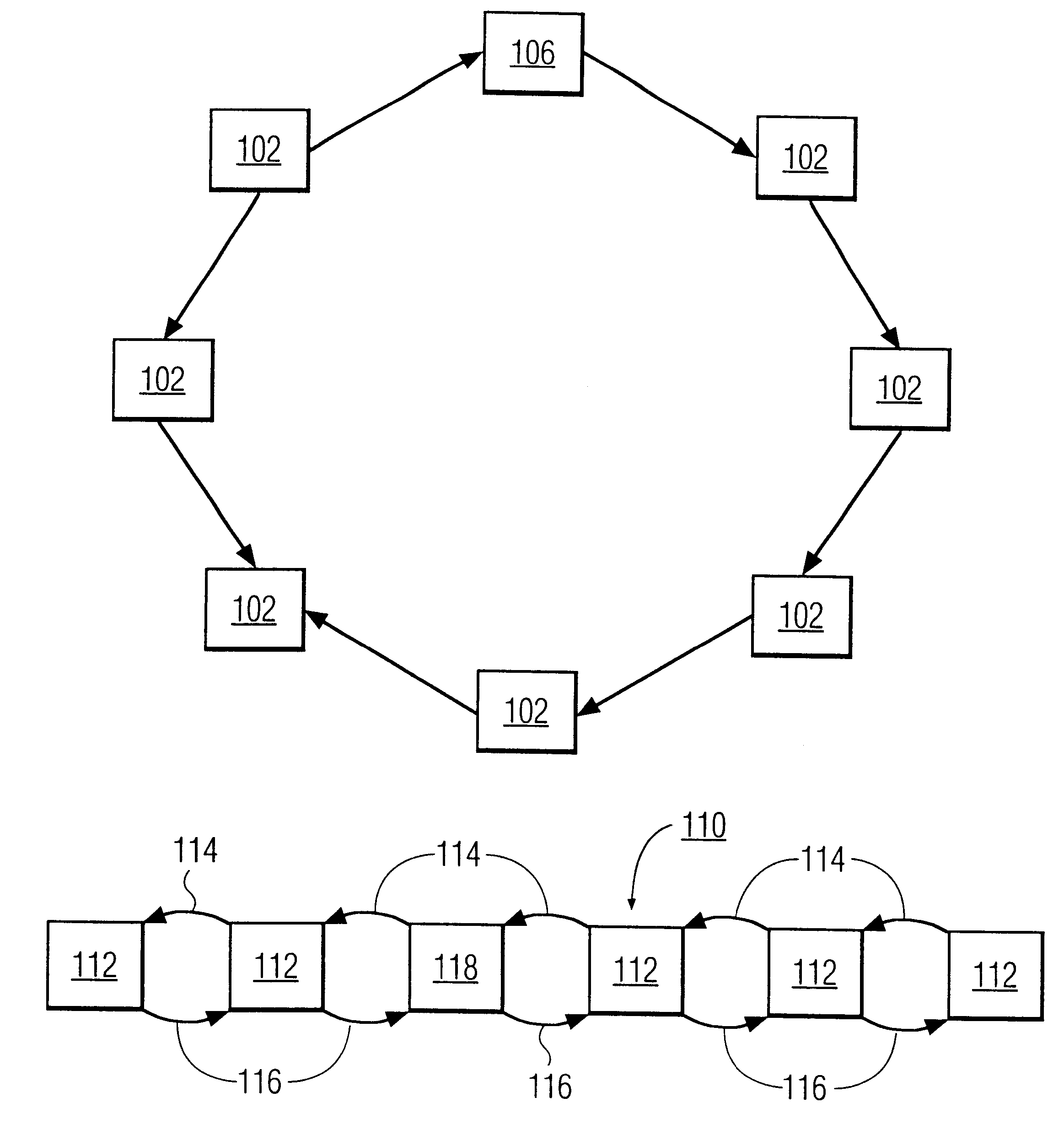
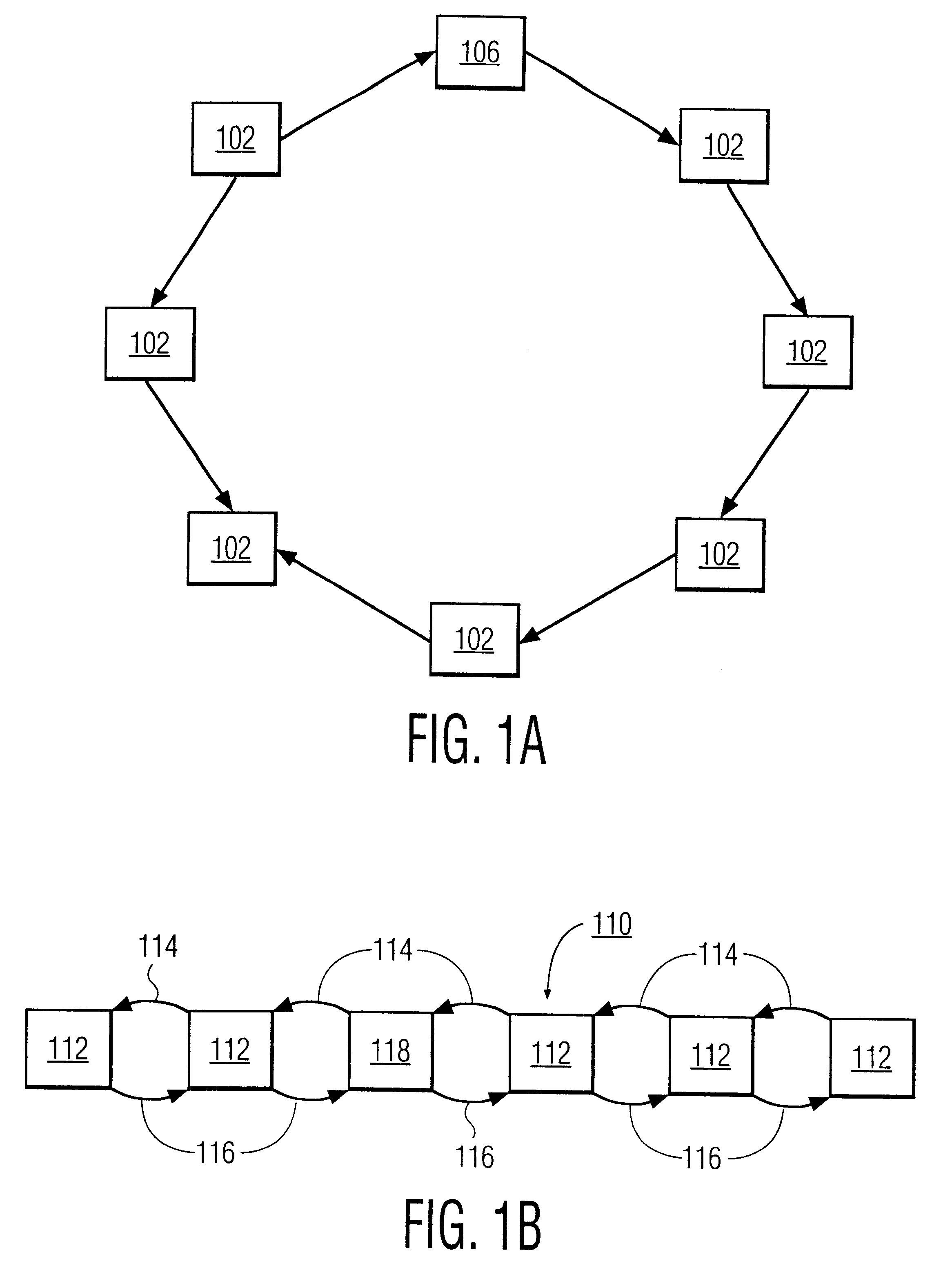
FIG. 1A is a block diagram of this invention with a network 100 having a plurality of nodes 102 and a node 106. The network 100 is designed in this example as a logical ring. The ring does not have to be an actual physical layout of nodes. The diagram illustrates an abstract or logical node layout. Thus, it should be recognized that the nodes can be in different locations e.g., in different offices, buildings, cities, states or even in different countries. Moreover, the communication pathways connecting the nodes do not have to be in any particular arrangement provided that each node can communicate with its successor, and with all other active-nodes on the network in a broadcast fashion.

Each node 102, 106 has a copy of a polling protocol for propagating a polling token along communication pathways 104. The communication pathways 104 can be of any type of wired connections such as twisted pairs, coaxial cable, fiber optics, phone lines, DSN, T1, T2, T3 or the like, or any type of wi...

second embodiment

FIG. 1B is a block diagram of a network of this invention including a network 110 having a plurality of nodes 112. The network 110 is designed as a logical chain. Each node 112, 118 has a copy of a polling protocol for propagating a polling token along forward pathways 114 and backward pathways 116. If all of the nodes 112, 118 are active the polling message will propagate along the chain until a break occurs. The chain configuration requires the protocol to have a forward successor address used with the forward pathways 114 and a backwards successor address used with the backwards pathways 116. Stated differently, each node 112, 118 has the address of its successor for use in forward propagation and the address of its predecessor for use in backward propagation. At the chain ends, the successor address and predecessor address is the same.

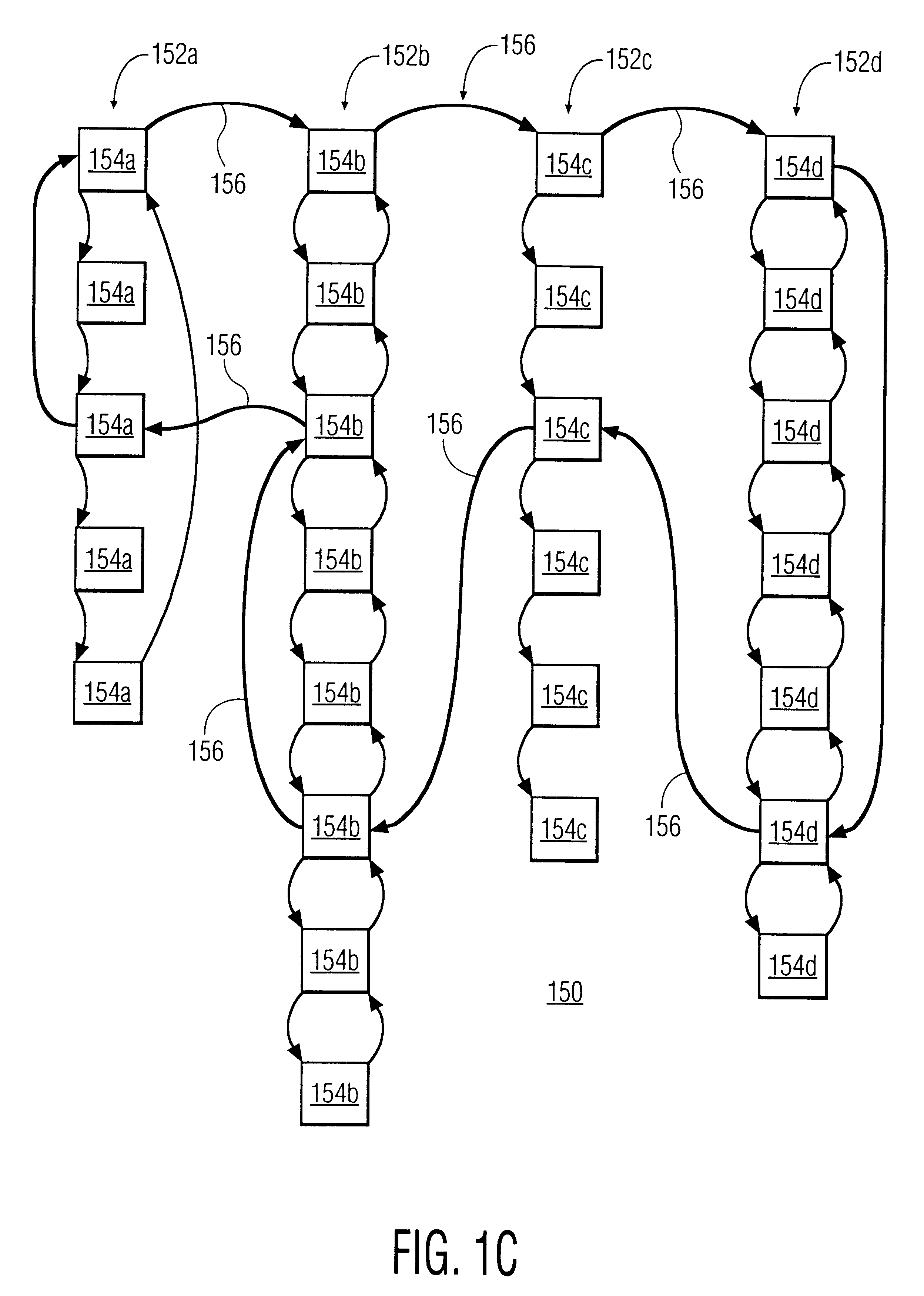
FIG. 1C is a block diagram of a super network 150 with a plurality of linked-node networks 152a-d. Each network 152a-d includes a plurality of nod...


PUM


Abstract

The present invention involves a network polling protocol which treats the network as a logical ring or linear sequence of nodes linked together so that a polling request is simply propagated down or around the network one node at a time until a complete inventory of active nodes is achieved. The protocols also includes procedures for curing or repairing breaks in the linking protocol and for adding new nodes to the linking protocol. The linking protocol can also be used to establish hierarchal linked networks where top level hierarchies includes addresses to a permanent member of a linked network and bottom level hierarchies are a given linked network.

Description

The invention relates to an information processing system comprising a plurality of information processing nodes, wherein the nodes are functionally connected to form a network. The invention also relates to a method of enabling operation of an information processing system having a network with a plurality of information processing nodes.It is known to use a broadcast protocol to verify the presence of active nodes in a network. Broadcast protocols work by sending a message to all nodes and requesting response. If a particular node needs to know what nodes are active in the network, the node broadcasts a message to all other nodes and waits for the nodes to respond to the broadcast. However, broadcast protocols are not reliable for several reasons.First, there is no guarantee that all relevant nodes have received the message. Broadcast protocols typically rely on a best-effort-delivery assumption. Such best-effort-delivery procedures generally are not set up to ensure or verify tha...

Claims


Application Information

Patent Timeline
IPC IPC(8): H04L12/56H04L12/24H04L12/427
CPCH04L12/24H04L41/00H04L45/02
Inventor CHAMBERS, PAULCURRY, STEVEN
Owner KONINKLIJKE PHILIPS ELECTRONICS NV
Learn More