
Elevator brake load weighing system

a technology of weighing system and elevator, which is applied in the direction of elevators, instruments, transportation and packaging, etc., can solve the problems of affecting the safety of elevators, etc., and achieves the effects of improving the measurement of the reaction torque of elevator brakes, reliable, and requiring little maintenan

Inactive Publication Date: 2002-11-19
OTIS ELEVATOR CO
View PDF9 Cites 22 Cited by
  • Summary
  • Abstract
  • Description
  • Claims
  • Application Information

AI Technical Summary

Benefits of technology

Objects of the invention include provision of improved measurement of elevator brake reaction torque, with apparatus which is reliable, inexpensive, and requiring little maintenance; determining whether the live load in the car exceeds maximum permissible load while the brake is still engaged; and providing a simple method for extracting the live load of an elevator from elevator motor shaft load measurements, for use in motion control and dispatching algorithms.

Problems solved by technology

However, the methods used heretofore to eliminate contributions of ropes, chains and cables are very complex, cumbersome and time consuming.
Use of the current that balances torque to determine whether or not a live load exceeds the maximum permitted load for the car, since it can be measured only with brake off, can be dangerous, and may violate some regulatory codes.

Method used


Image

  • Elevator brake load weighing system
  • Elevator brake load weighing system
  • Elevator brake load weighing system

Examples


Embodiment Construction

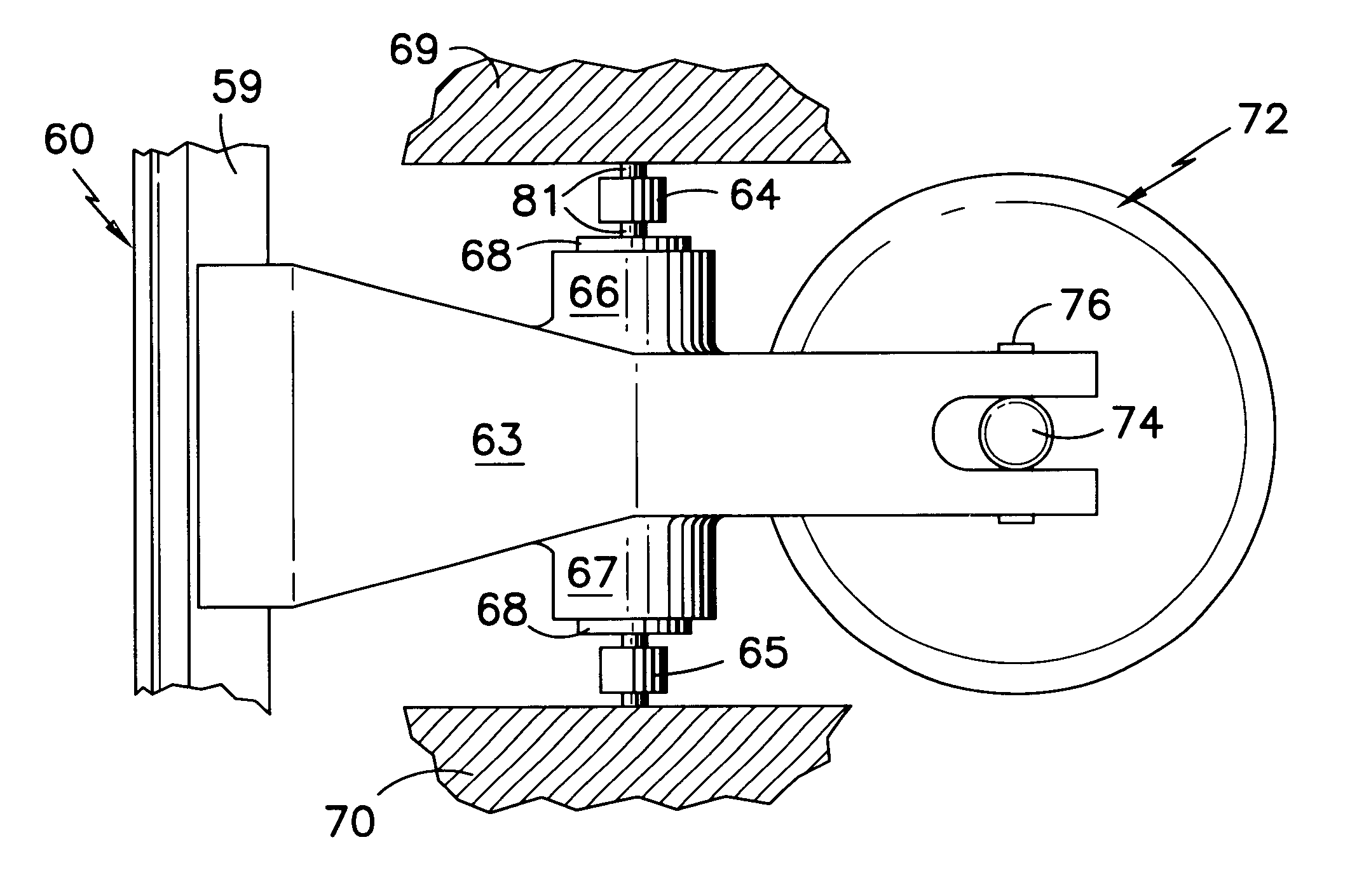
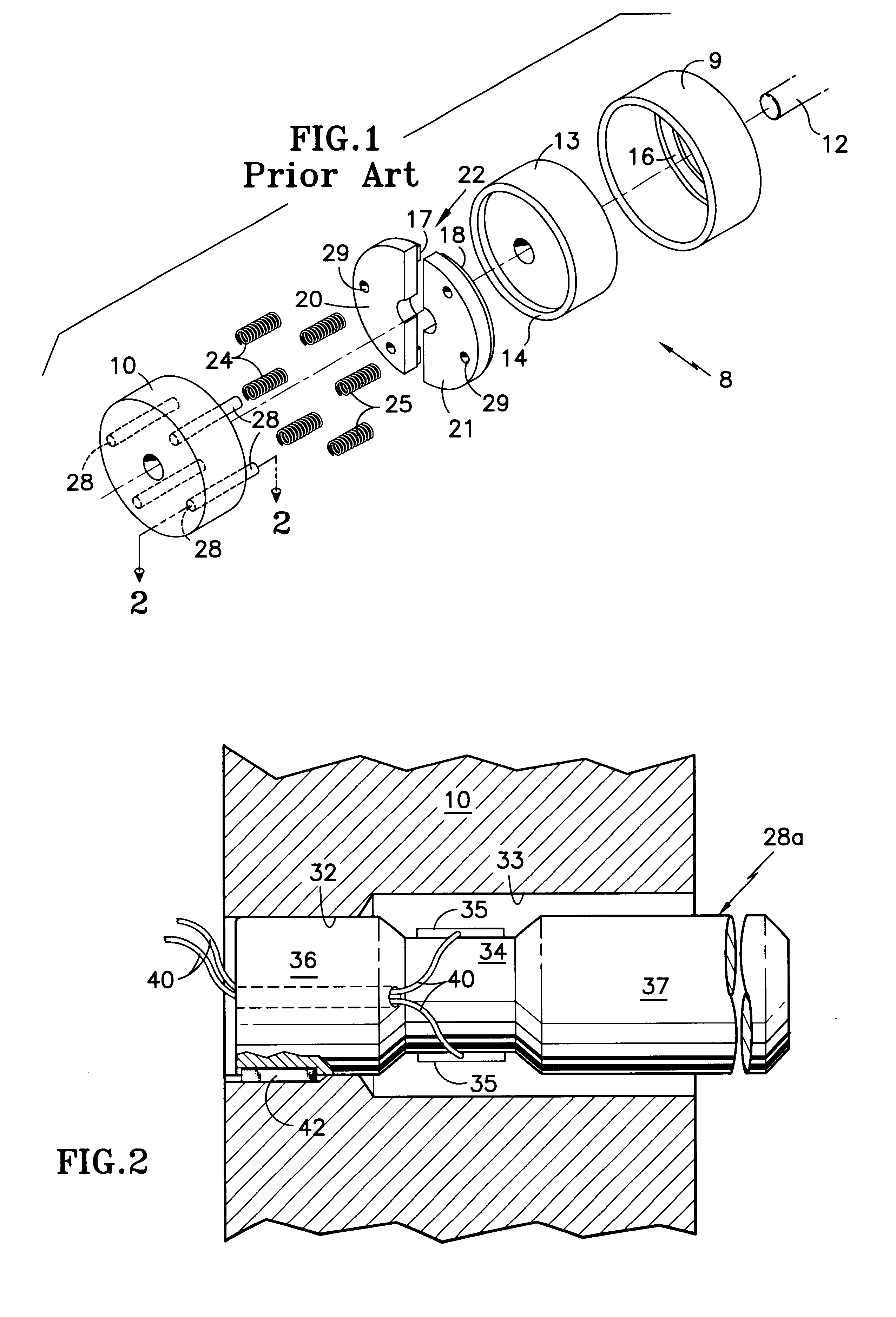
Referring to FIG. 1, an elevator disk brake assembly, shown in FIG. 1 in a stylistic manner for clarity, includes a housing 9 and a cap 10 for the housing: the cap 10 comprising an electromagnetic coil which, when energized, will release the disk brake so the elevator can move; the cap 10 is bolted or otherwise firmly secured to the housing 9 by bolts or other means not shown. The housing 9, with the cap 10, is generally fixed to the structure of the elevator drive system, such as directly attached to the elevator motor housing or otherwise. The elevator motor shaft 12 is splined or otherwise connected with a bifacial brake disk 13 so that the disk 13 always rotates with the shaft 12 and thereby can arrest the motion of the shaft 12. Disk 13 must be able to slide along the shaft 12 sufficiently so as to engage and release the brake, as is described more fully hereinafter. The bifacial brake disk 13 has two disk surfaces, one of which 14 is visible in FIG. 1, and the other being on t...


PUM


Abstract

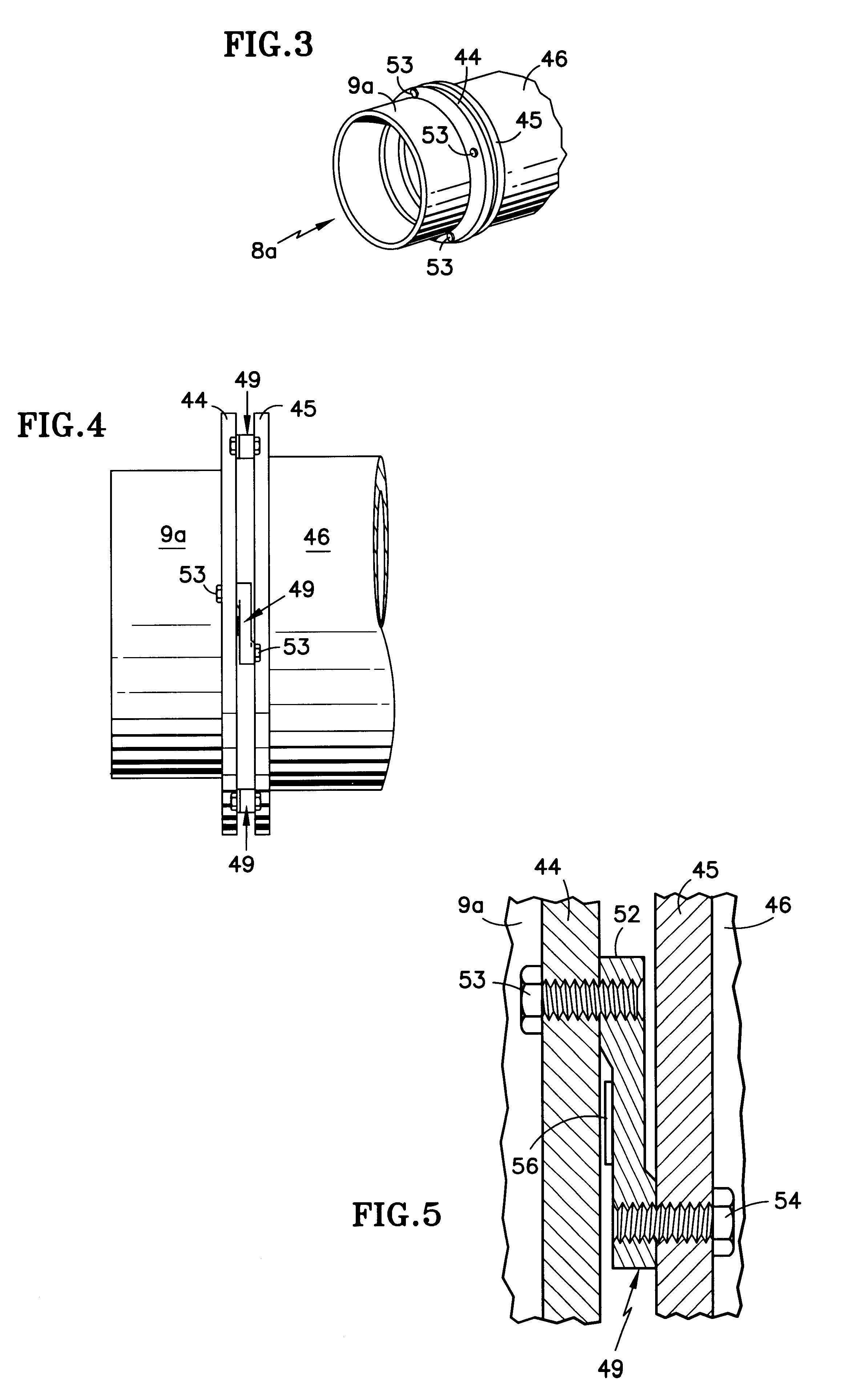
Load cells 35, 56 on antirotation dowel pins 28a or load mounts 49 indicate brake reaction forces in the disk brake 8, 8a of an elevator. Vertical load cells 72, 73 on bending load cell 80 indicate vertical brake reaction loads on a rail 60. A table indicating the load of an empty car at each of the landings served by the car permits subtracting load components relating to ropes, chains and cables to provide a live load indication prior to brake release; this may be used to determine if the load exceeds the maximum permissible load for the car.

Description

This invention relates to measuring elevator load by load cells integrated with elevator brake anti-rotation pins, brake mountings, and calipers, and measuring elevator car line load therewith.It has been shown in U.S. Pat. No. 3,610,342 and 4,754,850 that elevator brake reaction force can be measured so as to pretorque the motor drive in a closed loop fashion so that the motor torque exactly balances the car load, and the magnitude of current that produces the balancing torque is indicative of the live load in the car (passengers), by taking out the contribution of hoist ropes, compensation ropes and chains, and traveling cable. This can then be used to govern the generation of motor commands by the motion controller, and may be used as well for an indication of numbers of passengers in a car which is useful in dispatching algorithms. However, the methods used heretofore to eliminate contributions of ropes, chains and cables are very complex, cumbersome and time consuming. It is ne...

Claims


Application Information

Patent Timeline
IPC IPC(8): G01G19/00G01G19/18
CPCG01G19/18
Inventor ZAHARIA, VLADMORRIS, NIGEL B.
Owner OTIS ELEVATOR CO
Learn More