
Assembly and process for controlled burning of landmine without detonation

a technology of controlled burning and landmines, which is applied in the direction of self-propelled projectiles, weapons types, weapons, etc., can solve the problems of insufficient effectiveness of humanitarian efforts to demine planted landmines in order to protect civilian interests, and the inability to detonate landmines, etc., to achieve the effect of outpacing current demining efforts and ensuring the safety of civilians

Inactive Publication Date: 2002-11-26
NORTHROP GRUMMAN INNOVATION SYST INC +1
View PDF35 Cites 21 Cited by
  • Summary
  • Abstract
  • Description
  • Claims
  • Application Information

AI Technical Summary

Benefits of technology

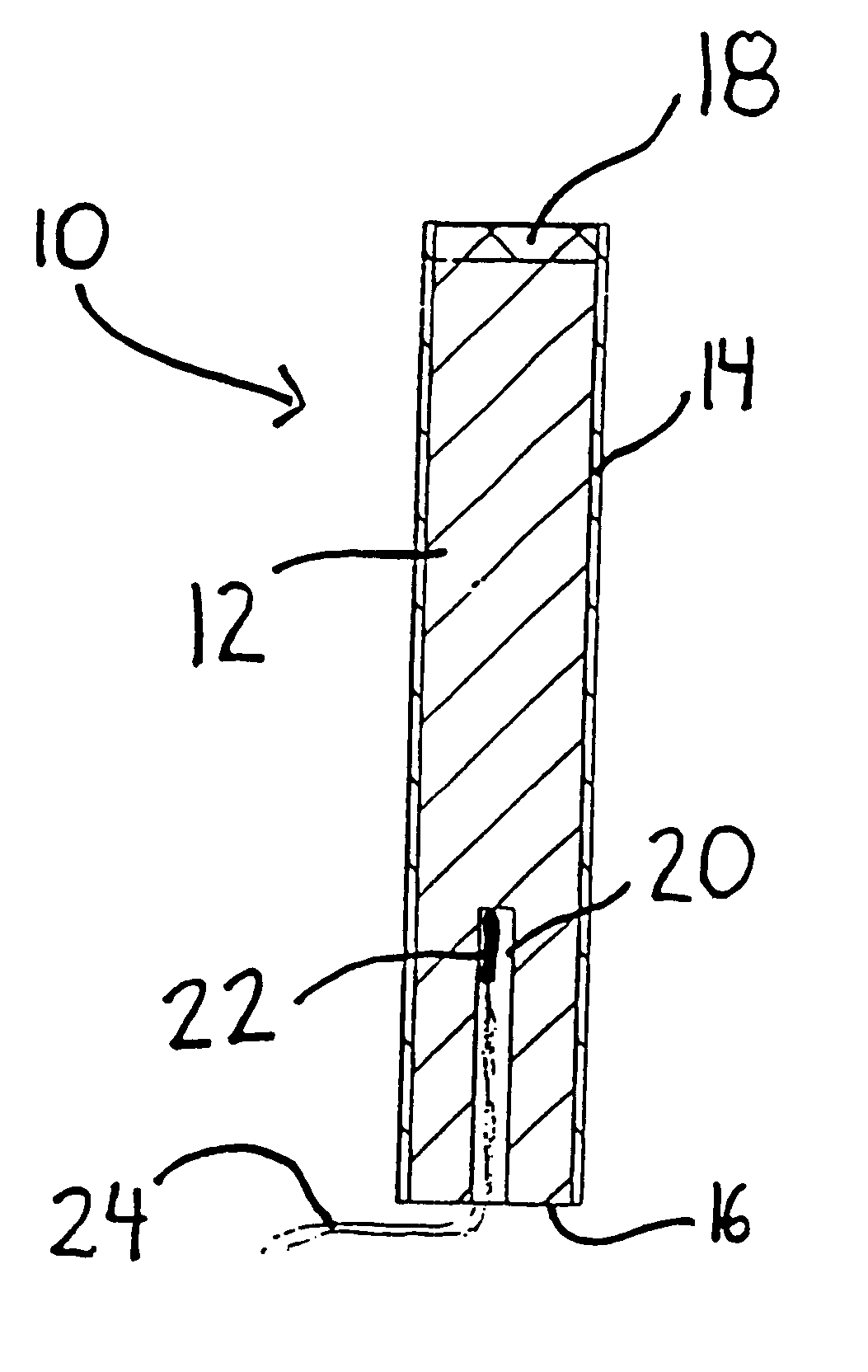
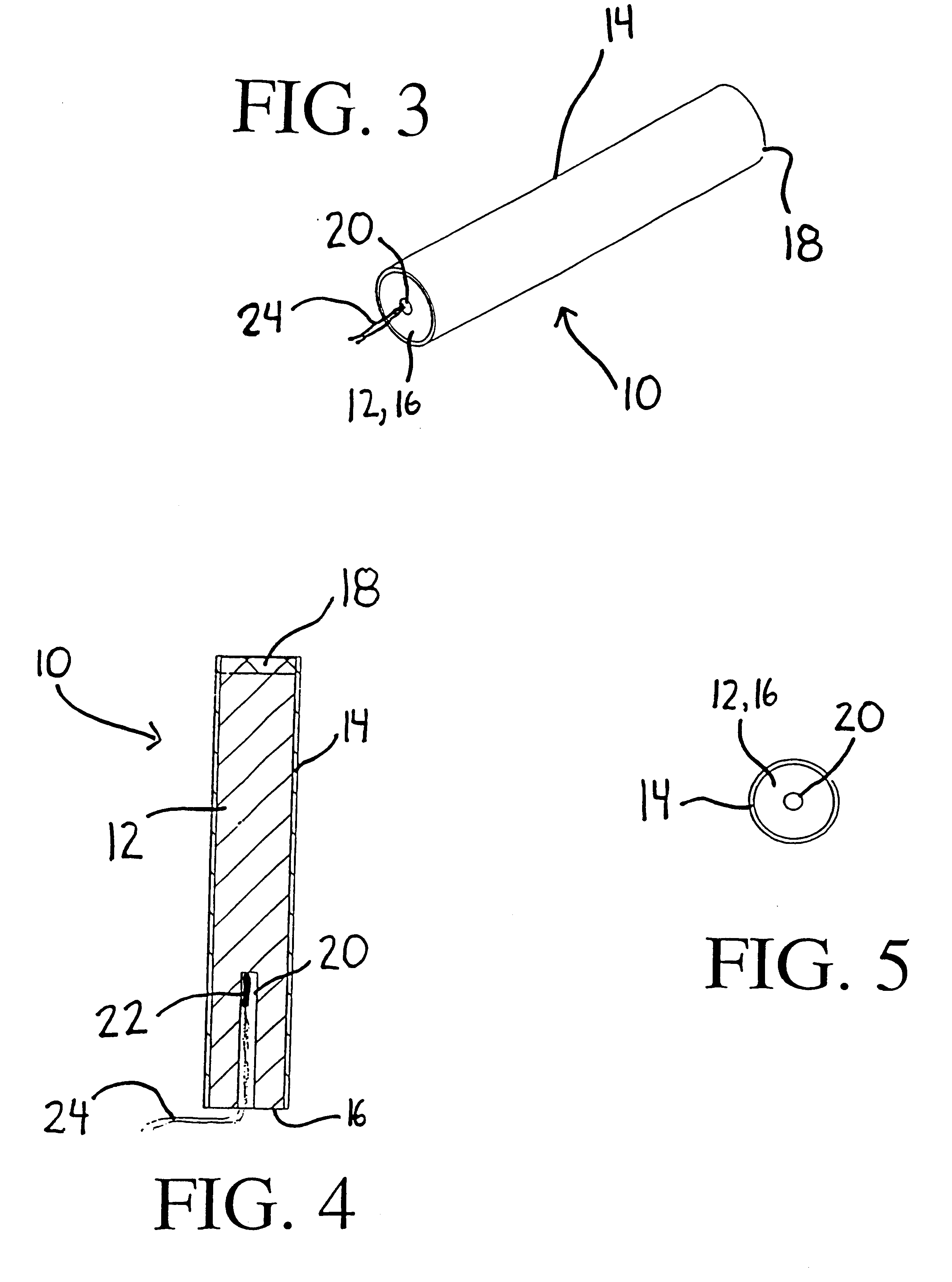
The solid propellant 12 selected should be present in an amount and composition suitable for generating a plume sufficient in burn time and temperature both to penetrate through the case of the landmine positioned in spaced relation to the lower end 16 and to initiate controlled burning of the explosive charge of the landmine. Additionally, the solid propellant 12 preferably is non-explosive, meaning that its explosive rating is Class 1.3, or even lower (at Class 1.4) to reduce handling and shipping costs. Although in the illustrated embodiment the solid propellant 12 has a central perforation 20, it is understood that the solid propellant 12 can be end burning.
Absent from the lower end 16 of the housing 14 is a nozzle throat capable of creating internal pressure and thrust of sufficient velocity to detonate the landmines. In this manner, the plume created by the assembly 10 serves to melt the landmine case and initiate burning the landmine explosive, rather than impinging on the landmine with sufficient force to dislodge and / or detonate the landmine (which is the object of U.S. Pat. No. 4,008,644) or make the assembly 10 propulsive.
The initiator 22 is positioned in operative communication with the central perforation 20 of the solid propellant 12. Preferably, the initiator 22 is remotely operable. Suitable initiators 22 include electric matches with lead line (24) or standard fuse cords of sufficient length to allow the operator to move away from the assembly 10 by a sufficient distance prior to initiation so as to avoid injury in the event of an accidental detonation of the landmine explosive.
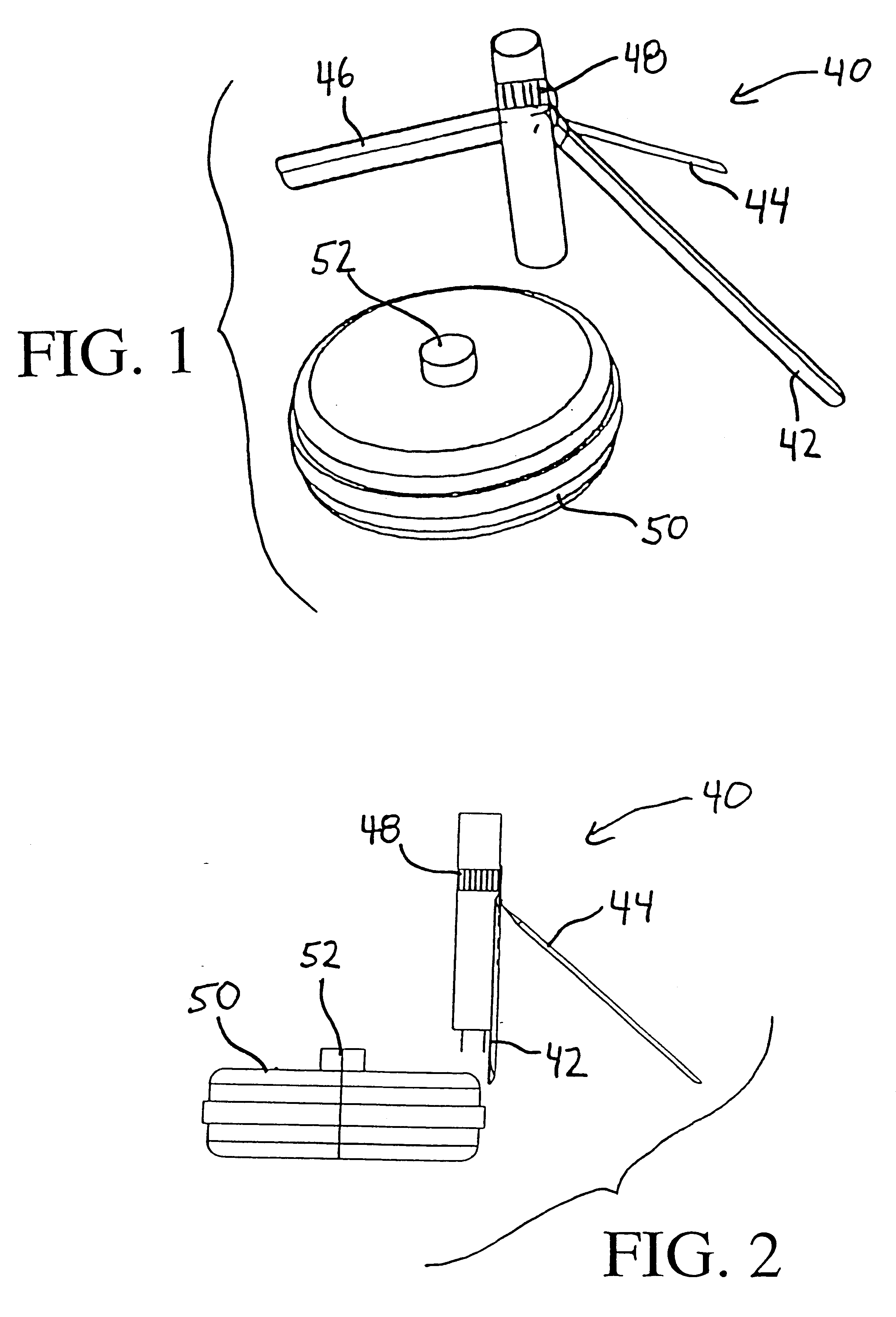
The illustrated tripod stand can be replaced with other devices and apparatuses for holding the landmine-neutralizing assembly 10. For example, as shown in FIGS. 6A and 6B, the illustrated hose clamp 48 can optionally be replaced by an upper end cap fitting 60. The end cap fitting 60 has an inner peripheral surface that is approximately the same diameter as the outer diameter of housing 14, so that the upper end cap fitting 60 is securely and tightly fitted over the upper end 18 of the housing 14 in use. The upper end cap fitting 60 has radially flanged portions 62 with apertures (or bores) 64a, 64b, 64c, and 64d formed therethrough. The apertures 64a-64d function to receive support wires (not shown) or the like. For example, a first piece of wire can extend from the ground up through the upper end cap fitting 60 so as to pass through the first aperture 64a. The wire can be configured substantially as an inverted "U" (or horseshoe shape), so that the wire passes downward through the second aperture 64b and extends back to the ground. A second wire can be used in a similar manner and passed through third and fourth apertures 64c and 64d, so that the wires collectively form a pod or stand having four legs. Of course, more radially flanged portions and apertures can be provided around the circumference of the end cap fitting 60 to receive additional wires and increase the stability of the stand still further. In addition to the structural stability provided by this upper end cap fitting, another advantage of this particular embodiment is that the adhesive sealant provided at the upper end 18 becomes redundant in function to the end cap fitting, and therefore can be excluded from the assembly 10 to further reduce costs.

Problems solved by technology

There are many currently active military conflicts for which landmines are being produced and planted.
Additionally, in many parts of the world in which military conflicts have been resolved and landmines are no longer needed for military operations, the landmines nonetheless remain planted, active, and often forgotten.
To date, humanitarian efforts to demine planted landmines in order to protect civilian interests have not been sufficiently effective.
One of the principle reasons, if not the principle reason, that the proliferation and planting of new land mines has outpaced current demining efforts is the relatively high cost and complexity of current demining devices.
The high cost and complexity that characterizes current demining devices make the conventional devices impractical for use in third world countries, where landmines are most prevalent.
Third world countries are often unable to both afford conventional demining devices and find or afford adequately skilled personnel for operating the complex conventional demining devices.
Another problem which characterizes conventional demining devices is that the conventional demining devices accomplish their demining objective by the detonation of active landmines.
However, these devices operate by effecting the violent detonation of active landmines, which presents safety hazards, including the potential for collateral damage as well as scattering of debris that may further complicate location and neutralization of other landmines.
However, road-side flares exhibit high variability in performance when tested on different types of landmines and landmine cases.
As a consequence, the use of road-side flares in controlled demining operations has been limited.
However, complete consumption of the explosive charge via burning cannot always be assured, since heat build up within the landmine case can cause inadvertent detonation of the explosive charge in some cases.

Method used


Image

  • Assembly and process for controlled burning of landmine without detonation
  • Assembly and process for controlled burning of landmine without detonation
  • Assembly and process for controlled burning of landmine without detonation

Examples


Embodiment Construction

has been provided for the purpose of explaining the principles of the invention and its practical application, thereby enabling others skilled in the art to understand the invention for various embodiments and with various modifications as are suited to the particular use contemplated. The foregoing detailed description is not intended to be exhaustive or to limit the invention to the precise embodiments disclosed. Modifications and equivalents will be apparent to practitioners skilled in this art and are encompassed within the spirit and scope of the appended claims.


PUM


Abstract

An assembly and process designed to neutralize a landmine having a case loaded with an explosive charge set to detonate upon actuation. The assembly includes a housing provided with a chamber loaded with a solid propellant. One of the ends of the housing is exposed to permit the loaded propellant to communicate the chamber with the outside atmosphere. The propellant is remotely ignitable via a remotely operable igniter. The first end of said housing is constructed and arranged and the solid propellant is present in an amount and composition suitable for generating, upon ignition of the solid propellant, a plume sufficient in burn time and temperature both to penetrate through the case of the landmine positioned in spaced relation to the first end and to initiate controlled burning of the explosive charge of the landmine so that detonation of the explosive charge is either avoided or reduced due to pre-detonation partial consumption of the explosive charge by burning.

Description

1. Field of the InventionThis invention relates to an assembly and process for effecting demining operations, and in particular to an assembly and process for at least partially consuming the explosive within a landmine in a controlled and stable manner so that detonation of the explosive is avoided or reduced in magnitude.2. Description of the Related ArtSince the development of landmines in World War I, landmines have found widespread military use as an effective deterrent to the advancement of enemy group troops during war time. For this purpose, anti-personnel landmines and anti-tank landmines are both known. Although the number of landmines currently actively used in the United States is negligible, landmines are quite abundant in many foreign countries. There are many currently active military conflicts for which landmines are being produced and planted. Additionally, in many parts of the world in which military conflicts have been resolved and landmines are no longer needed f...

Claims


Application Information

Patent Timeline
Patent Type & Authority Patents(United States)
IPC IPC(8): F42B33/00F42B33/06F42B3/00F41H11/12
CPCF41H11/12F42B3/00F42B33/067
Inventor ANDERSON, RICHARD C.ZISETTE, CHARLES B.CICCARELLI, ROBERT D.CRAGUN, RICHARD B.CRILLY, MICHAEL G.DELANEY, JR., JOHN E.
Owner NORTHROP GRUMMAN INNOVATION SYST INC
Learn More