Surface mount ring assembly for loudspeaker

Inactive Publication Date: 2002-11-26
OXFORD J CRAIG
View PDF55 Cites 62 Cited by
  • Summary
  • Abstract
  • Description
  • Claims
  • Application Information

AI Technical Summary

Benefits of technology

Broadly the invention embodies a mounting ring assembly for speakers. The ring assembly comprises a `hard` sleeve or ring in which the speaker is secured. This ring could be any suitable material, metal, polymeric material or the like. This sleeve in turn is secured to a resilient or `soft` ring which ring is secured in the wall opening. The ring may either be a ring such as described in my parent appli

Problems solved by technology

This method of installation is time consuming and costly.
When speakers are hard mounted into a wall or panel,

Method used


Image

  • Surface mount ring assembly for loudspeaker
  • Surface mount ring assembly for loudspeaker
  • Surface mount ring assembly for loudspeaker

Examples


Embodiment Construction

)

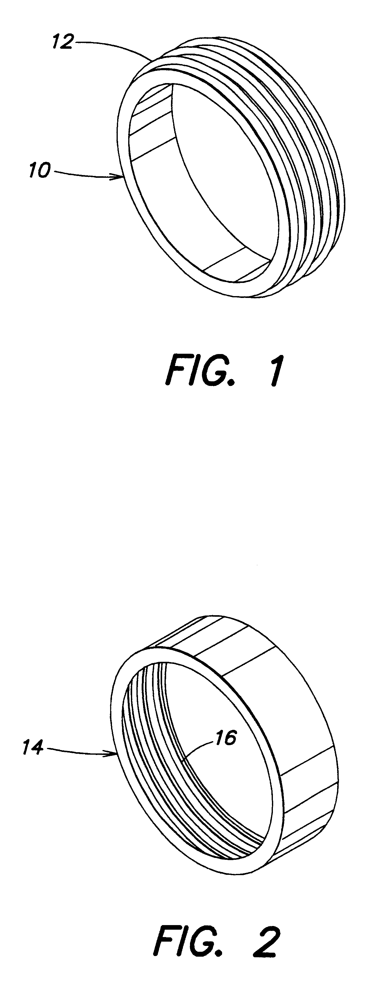
Referring to FIG. 1, a ring is shown at 10 and comprises a roughened outer surface characterized by ribs 12.

Referring to FIG. 2, a ring 14 has a roughened inner surface characterized by ribs 16.

Preferably the rings 10 and 14 are formed of an elastomeric material, a visco elastic elastomer, i.e. butyl rubber, having a durometer of between 30 to 90, preferably between 40 to 50, and a dynamic loss modulus of about 10.sup.10 Dynes / cm.sup.2 at 100 to 1000 Hz. The selection of the material results in the ability of the ring to reduce transmission of vibrations from the loudspeaker to the panel by providing isolation and damping. Also, the loudspeaker is isolated from the vibrations inherent in the structure in which it is secured, whether a wall panel or door panel.

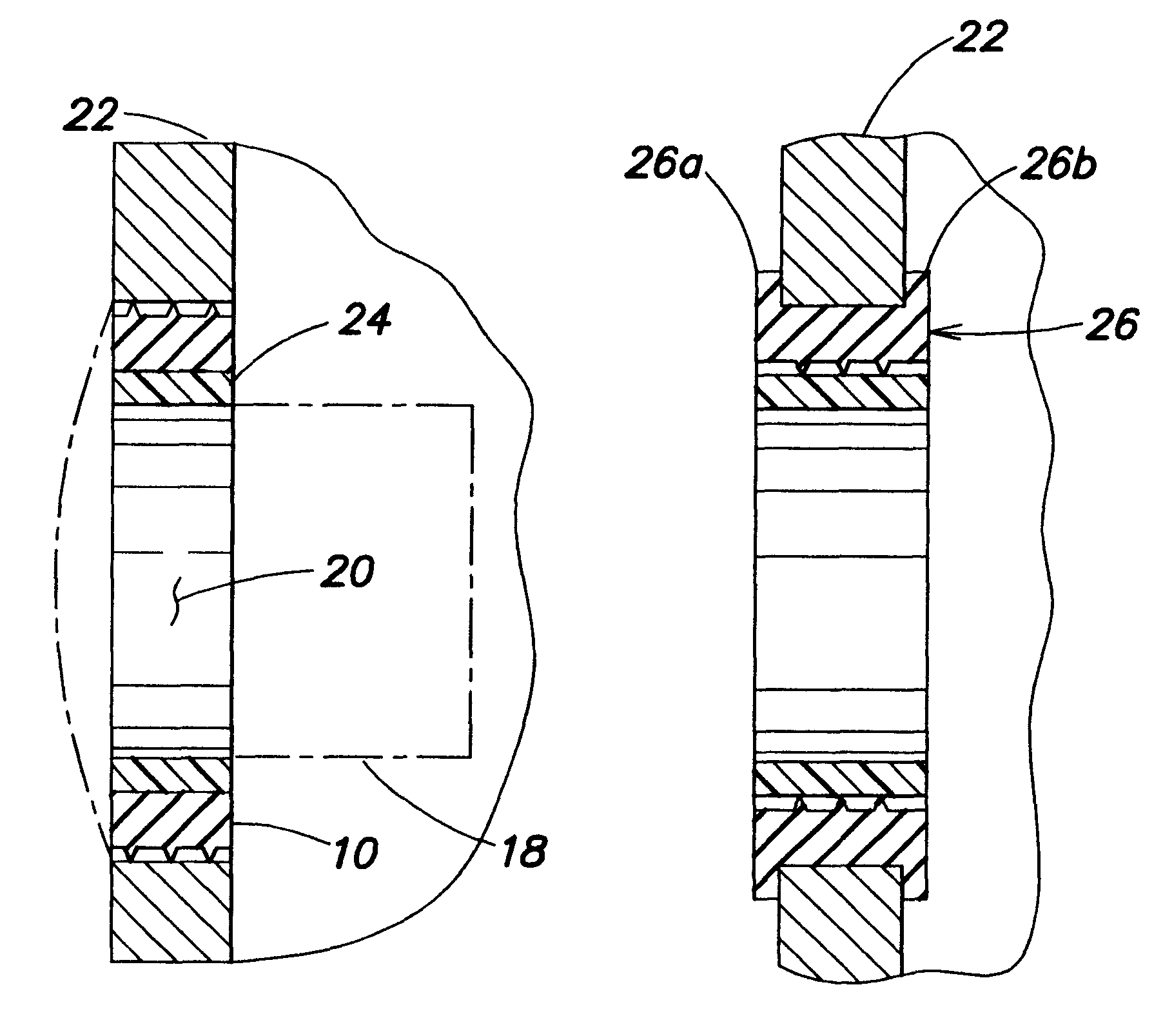
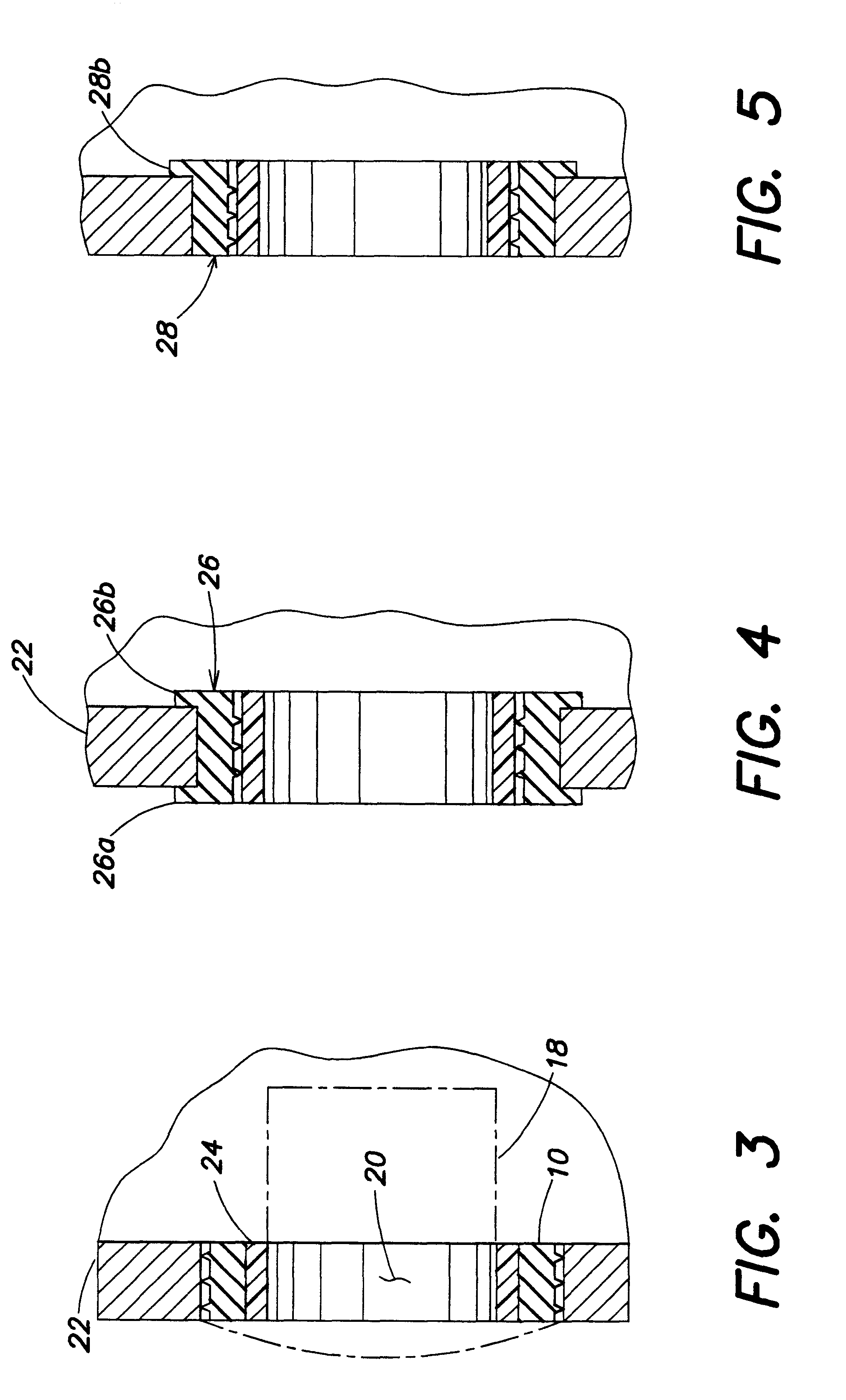
Referring to FIG. 3, a speaker 18 is shown in dotted lines. The ring 10 is secured in an opening 20 in a wall 22. A hard sleeve 24, e.g. a PVC tube, compression fits into the ring 10 fixedly securing the ring / sleeve into the w...


PUM


Abstract

A surface mount ring assembly for loudspeakers which comprises a "hard' ring in which the speaker is secured. This hard ring is, in turn, secured to a resilient or "soft' ring which soft ring is secured in the wall opening. The soft ring has a durometer of between 30 to 90 and a dynamic loss modulus of 1010 Dynes/cm2 at 100 to 1000 Hz. This effectively isolates the loudspeaker from the resonant frequency of the structure in which the speaker is secured.

Description

A mounting ring for a loudspeaker. The ring is frictionally fitted into a panel such as a wall or the interior panel of a vehicle. The loudspeaker is secured in the ring.BACKGROUND AND BRIEF SUMMARY OF THE INVENTIONIn architectural loudspeaker installations loudspeaker drivers are installed into the interior and inside walls of buildings. The existing practice involves the use of a subassembly baffle to which one or more drivers are mounted. The baffle is then attached to the wall by means of assembly to a rough-in box which has been placed inside the wall. The rough-in box is a structural frame which requires an opening in the wall approximating the size of the baffle subassembly.In the installation of loudspeakers in vehicles particularly in the aftermarket, holes are formed in the panels and a support structure is secured in the hole by fasteners, typically threaded fasteners. The loudspeaker is then secured to the support structure, again usually by threaded fasteners. This meth...

Claims


Application Information

Patent Timeline
IPC IPC(8): B60R11/02H04R1/02B60R11/00
CPCB60R11/0217H04R1/025B60R2011/0019Y10T16/05B60R2011/0047
Inventor OXFORD, J. CRAIG
Owner OXFORD J CRAIG
Why Eureka
Try Eureka