
Needle guide for ultrasound transducer

a technology for ultrasound transducers and needle guides, which is applied in the direction of ultrasonic/sonic/infrasonic image/data processing, tomography, ultrasonic/sonic/infrasonic diagnostics, etc. it can solve the problems of loose joints and failure to maintain proper needle alignmen

Inactive Publication Date: 2002-11-26
SANDHU NAVPARKASH
View PDF14 Cites 75 Cited by
  • Summary
  • Abstract
  • Description
  • Claims
  • Application Information

AI Technical Summary

Benefits of technology

An apparatus for guiding a needle in conjunction with an ultrasound imaging system has now been discovered which securely holds both the needle and the transducer and allows for steady relative horizontal movement between the needle and the transducer. The apparatus of the present invention provides steady movement and securely holds both the transducer and the needle guide during use by employing two parallel arms between which both the transducer and the needle guidance unit are held. These two arms while securely holding both the transducer and the needle guidance unit, allow for relative horizontal movement of the transducer and the needle guidance unit.
In a preferred embodiment, the opposite sides of the frame are parallel sides with outward flat surfaces which are affixed to the respective inside, flat surfaces of the arms. Having the two flat surfaces against each. other increases the overall stability and rigidity of the apparatus. Likewise, in the needle guide unit, the two opposite sides are flat parallel sides which are held flat against the inside, flat surfaces of the arms, also increasing the stability and rigidity of the apparatus.

Problems solved by technology

Such a joint can come loose and fail to maintain proper alignment of the needle.
Naturally, this can lead to problems during a medical procedure.

Method used


Image

  • Needle guide for ultrasound transducer
  • Needle guide for ultrasound transducer
  • Needle guide for ultrasound transducer

Examples


Embodiment Construction

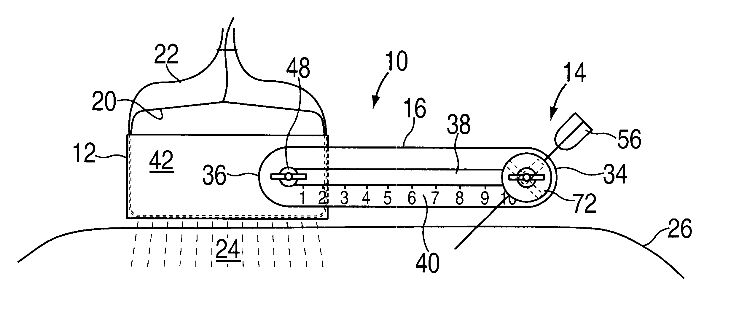
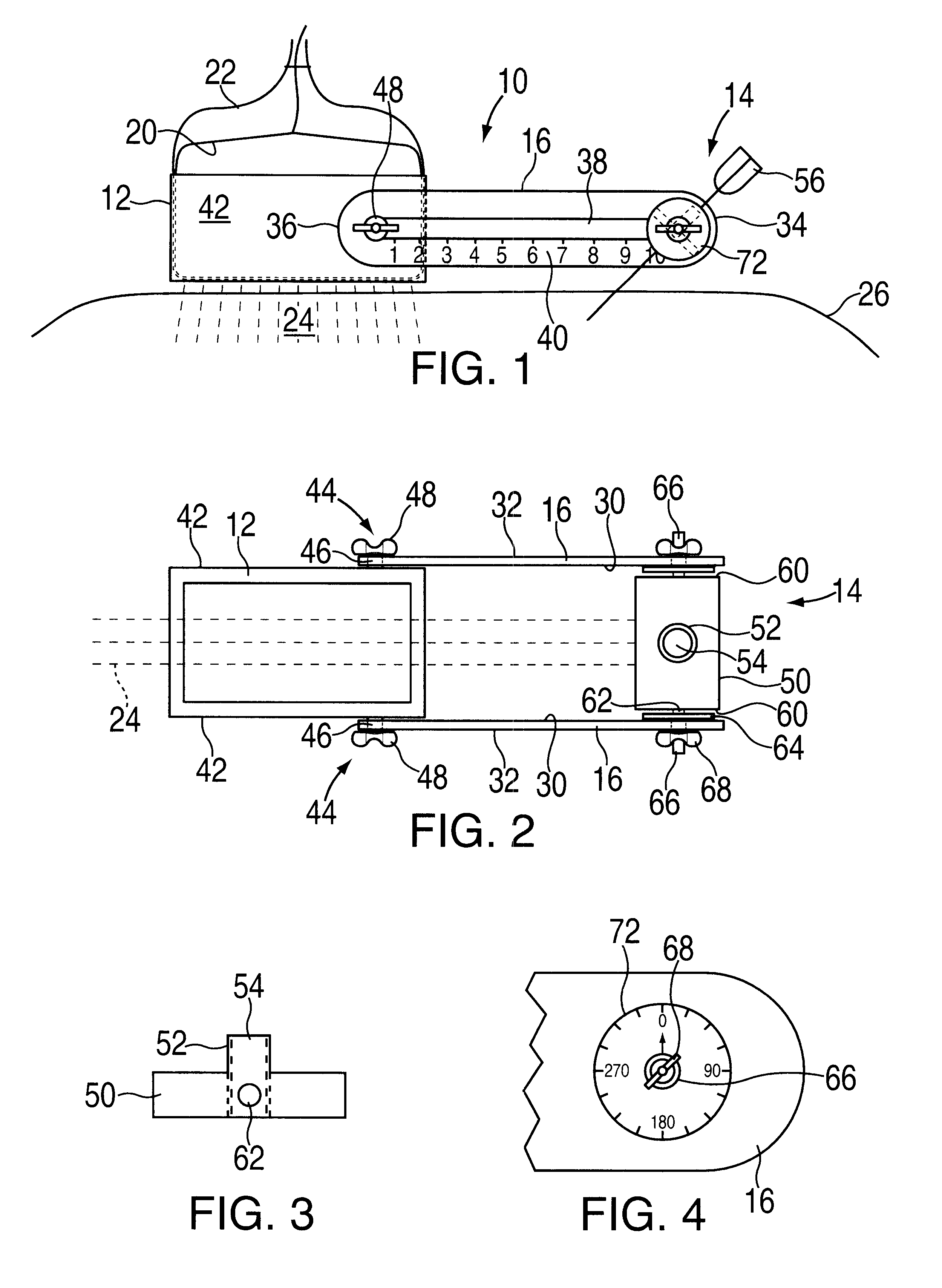
As shown in FIGS. 1 and 2, needle guidance apparatus 10 comprises box-shaped frame 12, needle guide unit 14, and two, parallel arms 16. Transducer 20 in latex bag 22 is securely held in frame 12 because of the frictional fit between the inside walls of frame 12 and the outside surface of transducer 20. Transducer 20 generates ultrasound beam 24 which is a planar beam that is vertically oriented in FIG. 1. Transducer 20 in frame 12 is held against body 26 of a patient.

Each arm 16 is generally rectangular in shape having vertical, flat inside wall 30, vertical, flat outside wall 32, two ends 34 and 36, and slot 38 therein which runs lengthwise in arms 16. Associated with each slot 38 is a gauge 40 for measuring and adjusting the distance or location between frame 12 and needle guide unit 14.

Frame 12 has vertical, flat outside walls 42. Extending outward from walls 42 is releasable fastener 44 which comprises bolt 46 with a respective wing nut 48. Bolt 46 extends from walls 42 of frame...


PUM


Abstract

A needle guidance device for use with an ultrasound transducer is made up of a frame for housing the transducer, a needle guide unit which has a sleeve in line with an ultrasound beam and two arms which affix the frame to the needle guide unit.

Description

BACKGROUND OF INVENTION1. Field of InventionThe present invention relates to an apparatus for keeping a needle aligned under an ultrasound beam and, more particularly, for guiding a needle used for administering anesthetic.2. Prior Art to InventionUltrasound systems for real time visual guidance of a needle into a patient's body are known and have been utilized for biopsies, drainage of fluids, amniocentesis, and the like. Generally, the physician uses one hand to hold the transducer against the body of the patient to visualize the target, and the other hand to guide the needle into the patient and hit the target. The ultrasound beam is planar in nature and visualizes the target and the needle as it comes close to the target.In order to steady the relative position of the transducer, the ultrasound beam, and the needle, various apparatuses have been suggested, see U.S. Pat. Nos. 4,899,756; 5,052,396; 5,076,279; 5,623,931; 5,758,650; 5,924,992; 5,928,219; and 5,941,889. Each of these...

Claims


Application Information

Patent Timeline
Patent Type & Authority Patents(United States)
IPC IPC(8): A61B17/34A61B8/08
CPCA61B8/0833A61B8/0841A61B17/3403A61B2017/3413A61B8/4209
Inventor SANDHU, NAVPARKASH
Owner SANDHU NAVPARKASH
Learn More