Insulator retainer

a technology of retainer and insulator, which is applied in the field of retainer, can solve the problems of wasting resources, increasing the chance of hitting your thumb or finger, and the fixing element must be directly held, so as to achieve less fiddly exercise, less time to be spent on exercise, and less loss of resources

Inactive Publication Date: 2002-12-03
GALLAGHER ELECTRONICS LTD CO
View PDF21 Cites 23 Cited by
  • Summary
  • Abstract
  • Description
  • Claims
  • Application Information

AI Technical Summary

Benefits of technology

An advantage of the present invention may have over existing insulators, is that the process of affixing insulators to support structures is facilitated rendering it less fiddly to undertake. Thus, the present invention also enables less time to be ...

Problems solved by technology

This results in either wasting resources by leaving the fixing element on the ground, or alternatively having to reach down and scramble around trying to find it on the ground, which can be difficult when working over rough ground.
Another drawback is that currently the fixing element must be directly held onto, to avoid it falling out.
This increases the chance of hitting your thum...

Method used


Image

  • Insulator retainer
  • Insulator retainer
  • Insulator retainer

Examples


Embodiment Construction

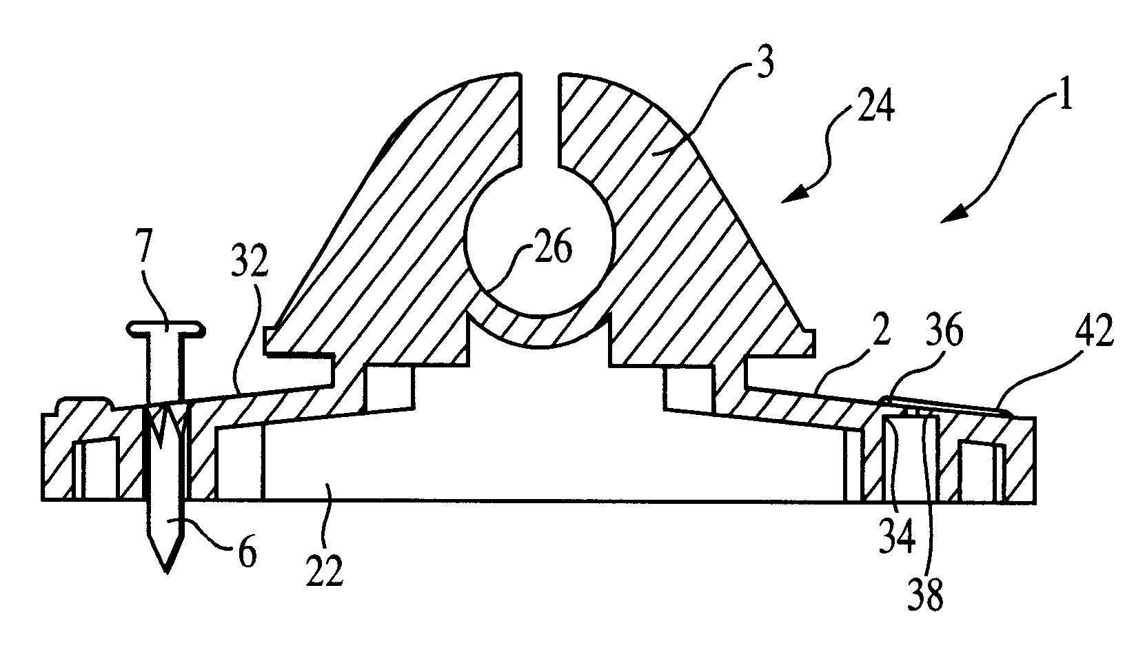
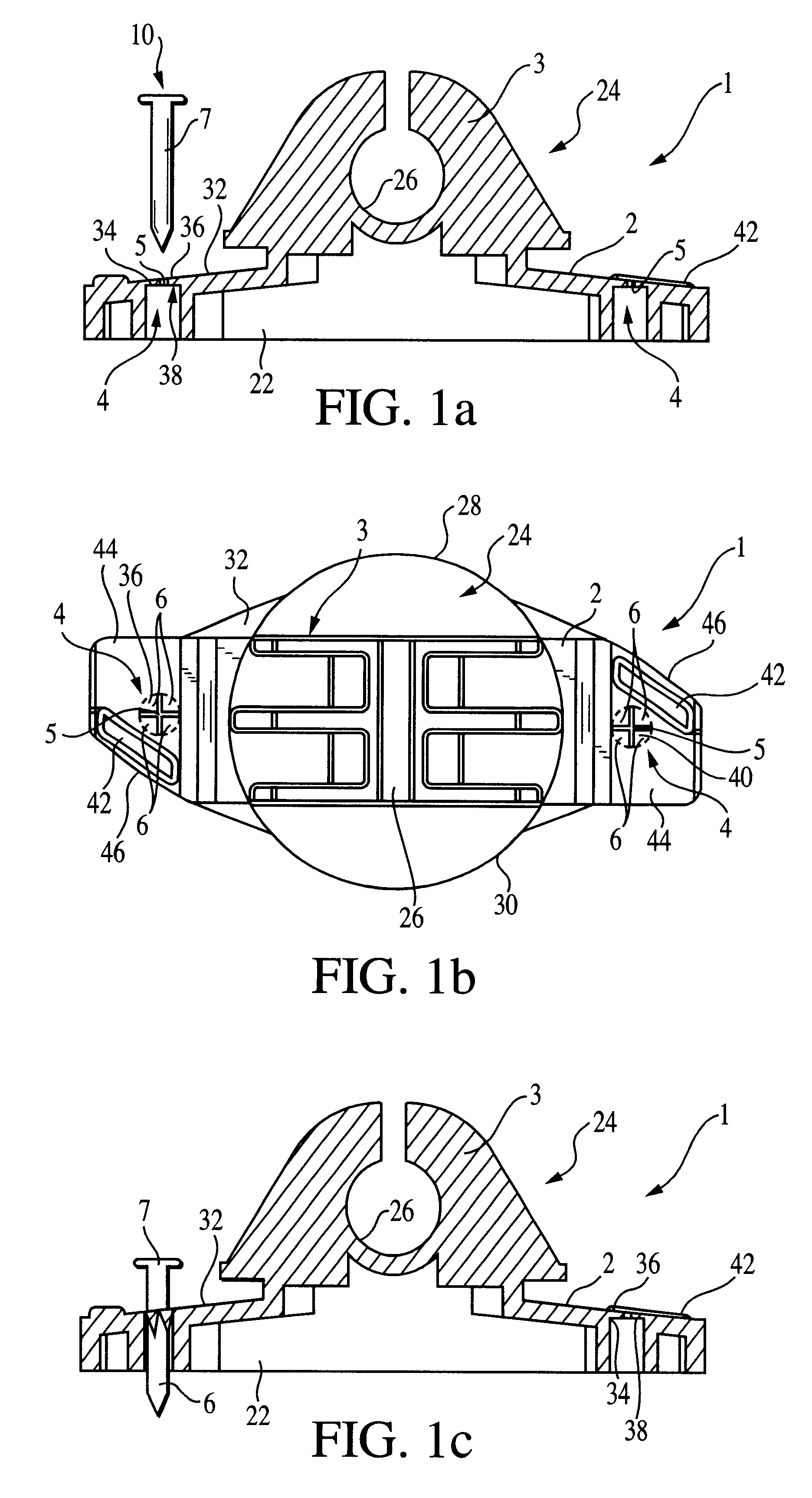
With respect to FIG. 1 there is illustrated in FIGS. 1a) and 1b) a side and plan view respectively of one preferred embodiment of insulator generally indicated by arrow 1.

The insulator 1 consists of a main body 2 and an electric fence wire support 3.

The main body 2 of the insulator 1 has two retaining-portions 4 consisting of an opening 5 which has four flaps 6 extending therein which have been demarcated by a dotted outline for ease of visual perception only.

In use a fixing element in the form of a nail 7 may be inserted into the retaining-portion 4 in the direction indicated by arrow 10.

Inserting the nail 7 into the retaining-portion 4 causes the flaps 6 to deform to accommodate the girth of the nail 7 as is shown in FIG. 1c). By this means the flaps 6 are able to, once the nail 7 has been inserted, frictionally engage the outer surface of the nail 7 to prevent it from dislodging from the insulator 1.

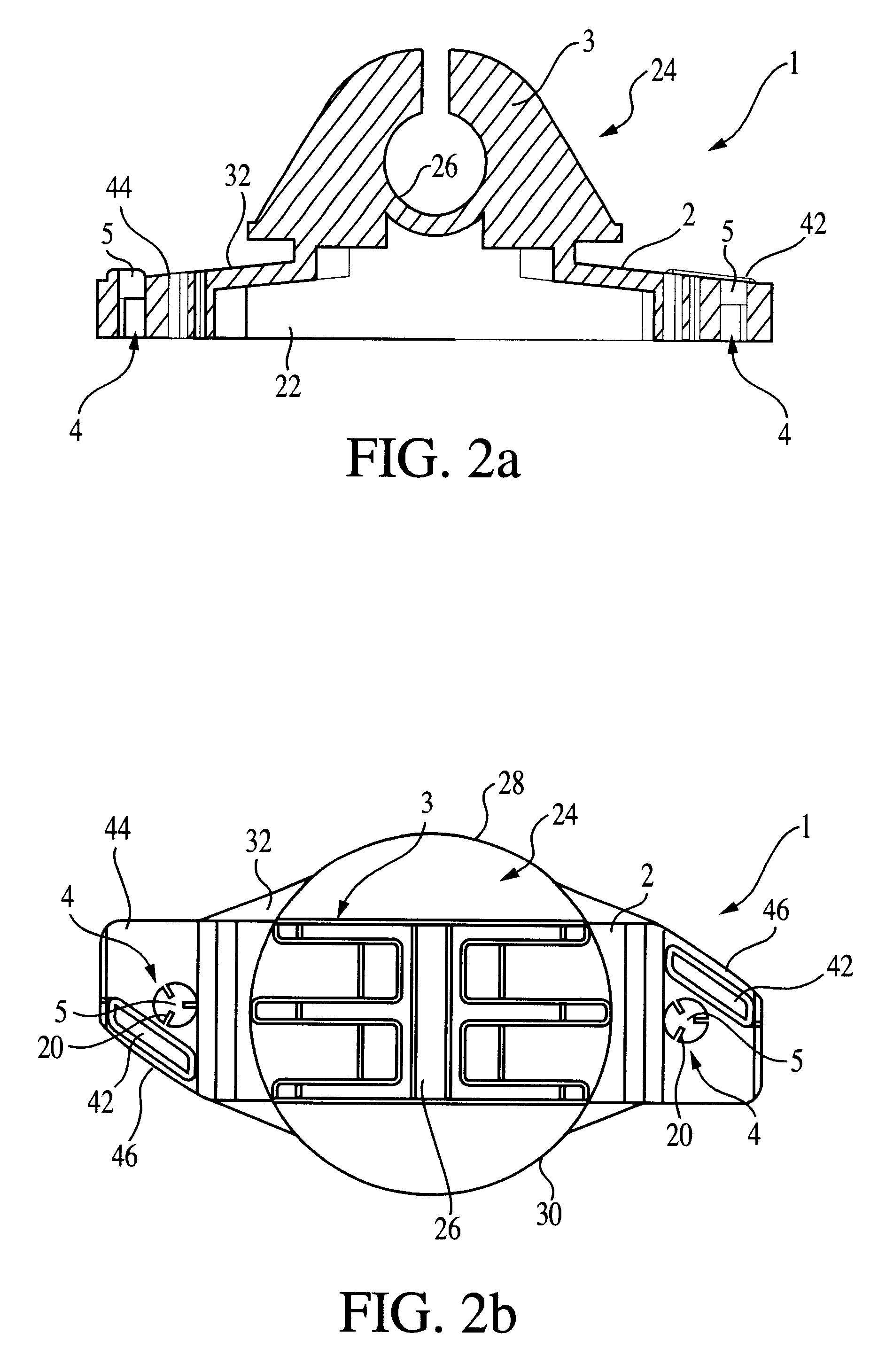
With respect to FIG. 2 there is illustrated in FIGS. 1a) and 1b) a side and plan ...


PUM


Abstract

An insulator capable of supporting the conductor of an electric fence including at least one retaining portion capable of retaining at least one fixing element to the insulator prior to the insulator being fixed to a support structure with the fixing element.

Description

Presently insulators are used to support the conducting material of electric fences. These insulators are generally secured to fence posts via screws, staples or other fixing elements.To secure insulators to posts generally requires a farmer to hold both the insulator and the fixing element. Understandably affixing the insulator to the support structures can be a fiddly affair. It is very easy to drop the fixing element while obtaining the device to engage the fixing element, for example a hammer, or a screwdriver. This results in either wasting resources by leaving the fixing element on the ground, or alternatively having to reach down and scramble around trying to find it on the ground, which can be difficult when working over rough ground.Another drawback is that currently the fixing element must be directly held onto, to avoid it falling out. This increases the chance of hitting your thumb or fingers during the process of fixing the insulator to the supporting structure, for exa...

Claims


Application Information

Patent Timeline
IPC IPC(8): H01B17/14
CPCH01B17/145Y10S411/97
Inventor THOMSON, BRADLEY JOHN
Owner GALLAGHER ELECTRONICS LTD CO
Why Eureka
Try Eureka