Noise reducing vortex generators on aircraft wing control surfaces

a technology of noise reduction and generators, which is applied in the direction of influencers by generating vortexes, airflow influencers, drag reduction, etc., can solve the problems of aerodynamically generated noise, aerodynamically generated noise, and aerodynamically generated noise. aerodynamically generated noise is especially significan

Inactive Publication Date: 2002-12-10
AIRBUS OPERATIONS GMBH
View PDF24 Cites 76 Cited by
  • Summary
  • Abstract
  • Description
  • Claims
  • Application Information

AI Technical Summary

Benefits of technology

In the inventive arrangement, the relatively small vortex generators arranged along the edges of the control surface purposely generate a greater number of relatively small individual vortices, which break-up and take energy away from the main vortex and thereby reduce the strength of the main vortex without significantly reducing the aerodynamic effect of the control surfaces and particularly the lift effect of the high lift flaps. The noise generated and radiated by the interaction of the various smaller vortex systems with the main surfaces and the surfaces or edges of the flap is significantly less than the noise generated by the undisturbed larger volume vortex system that would otherwise arise without the inventive vortex generators.
A substantial advantage of the invention is that relatively inexpensive and simple measures, with a relatively low construction and installation effort, achieve a significant noise reduction. In this context it is further advantageous, that the vortex generators according to the invention are easily adaptable with little effort, based on various factors such as the wing geometry, selected flight conditions, and the like, so that an efficient noise reduction can be achieved in a very simple and economical manner for various applications. A further advantage of the invention is that the subject vortex generators are rather light in weight, and in general hardly have any negative influence on the overall capacity or operation of the aircraft.

Problems solved by technology

A significant portion of the total noise generated by an aircraft in flight is caused by the flow of air along the external contours of the aircraft.
A large part of this aerodynamically generated noise is contributed by the flow of air over or along control surfaces of the aircraft.
The aerodynamically generated noise is especially significant and causes a disturbing influence in the surrounding environment, particularly in the landing approach of an aircraft, because in the landing configuration, the extended high lift flaps generate additional noise, and this noise is generated and radiated into the environment at a relatively low flight altitude.
This main vortex involves a relatively undisturbed, large-volume vortex flow of air, which radiates a significant amount of noise into the far field of the surrounding environment.

Method used


Image

  • Noise reducing vortex generators on aircraft wing control surfaces
  • Noise reducing vortex generators on aircraft wing control surfaces

Examples


Embodiment Construction

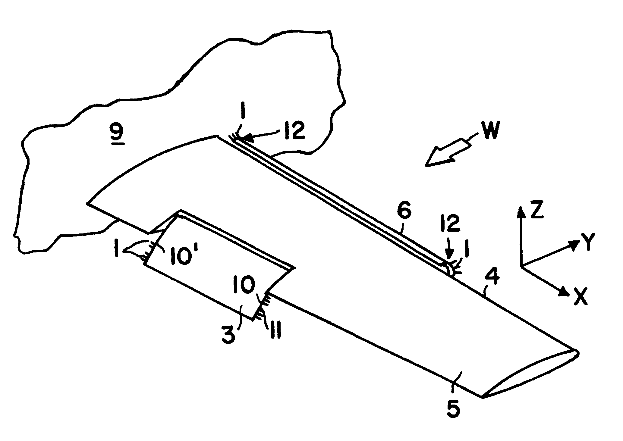
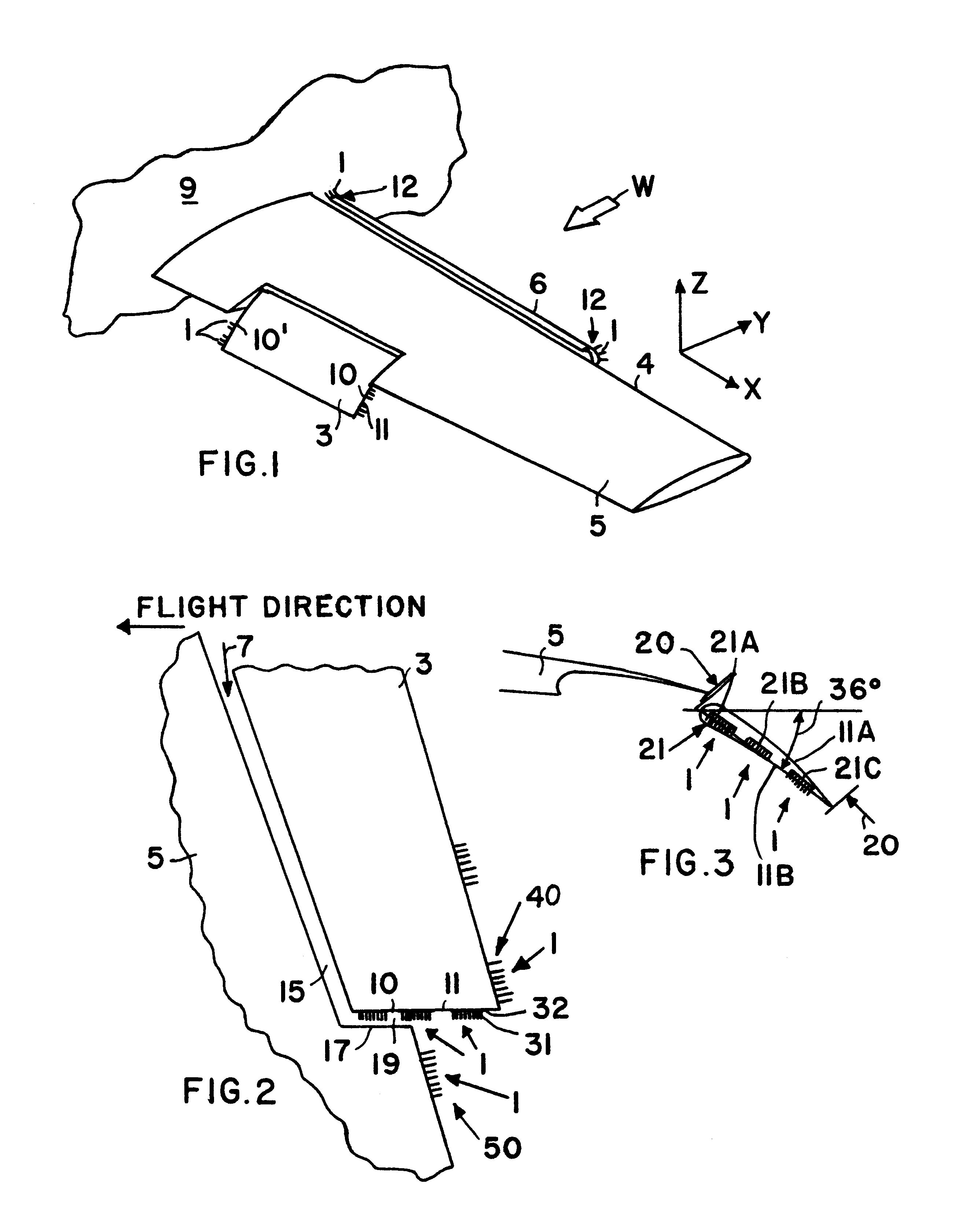
The inventive arrangement for reducing aerodynamic noise, especially by breaking up or interrupting a large main vortex flow, includes a plurality of vortex generators 1 arranged on a control surface, such as a high lift flap 3, for example, of a lifting wing 5 of an aircraft. For spatial reference, a Cartesian coordinate system of X, Y and Z-directions is indicated in FIG. 1, whereby the X-direction corresponds generally to the wing longitudinal direction or wingspan direction, and the Y-axis is perpendicular to the wing span direction, generally forward in the flight direction. The relative wind W approaching the leading edge 4 of the wing is also indicated. The inventive arrangement of vortex generators 1 is illustrated and will be described in connection with a high lift slat 6 and especially a high lift flap 3 as representative examples of control surfaces. It should be understood, however, that the pertinent control surfaces that may be equipped with vortex generators 1 accord...


PUM


Abstract

Vortex generators are arranged on the edges of aircraft wing control surfaces to generate smaller vortices that weaken the main vortex that would otherwise be generated at these areas, and thereby reduce the aerodynamic generation of noise. Each vortex generator includes plural elongated elements in the form of rigid rods or flexible bristles protruding laterally outwardly from the respective edge of the control surface. The vortex generators are preferably arranged on the inboard and outboard edges of high lift flaps and slats.

Description

PRIORITY CLAIMThis application is based on and claims the priority under 35 U.S.C. .sctn.119 of German Patent Application 100 20 177.6, filed on Apr. 25, 2000, the entire disclosure of which is incorporated herein by reference.1. Field of the InventionThe invention relates to an arrangement for reducing the noise generated by the aerodynamic flow of air over the lifting wings of aircraft, and particularly along the control surfaces such as high lift flaps or slats of such wings.2. Background InformationA significant portion of the total noise generated by an aircraft in flight is caused by the flow of air along the external contours of the aircraft. A large part of this aerodynamically generated noise is contributed by the flow of air over or along control surfaces of the aircraft. The aerodynamically generated noise is especially significant and causes a disturbing influence in the surrounding environment, particularly in the landing approach of an aircraft, because in the landing ...

Claims


Application Information

Patent Timeline
Patent Type & Authority Patents(United States)
IPC IPC(8): B64C21/00B64C23/00B64C23/06B64C21/10
CPCB64C21/10B64C23/06B64C7/00Y02T50/162Y02T50/166Y02T50/10
Inventor BORCHERS, INGODROBIETZ, ROGERGRUENEWALD, MICHAELMAU, KNUTREICHENBERGER, JOHANN
Owner AIRBUS OPERATIONS GMBH
Why Eureka
Try Eureka