
Device for transferring heat between a panel heated by solar radiation and a wall

a technology of solar radiation and a device, which is applied in the direction of solar heat collector controllers, solar heat collectors for particular environments, sustainable buildings, etc., can solve the problems of temperature reaching levels which, for certain materials, in particular insulation, are excessive, and single opening allows only very limited air exchang

Inactive Publication Date: 2002-12-17
RYLEWSKI EUGENIUSZ
View PDF11 Cites 11 Cited by
  • Summary
  • Abstract
  • Description
  • Claims
  • Application Information

AI Technical Summary

Benefits of technology

a closed state preventing circulation of air between the external space and the internal space and thus preventing thermal transfer between the panel and the wall.
The invention thus achieves mastery over the transfer of heat by convection while preventing the direct conductive and / or radiative contact between the panel and the wall by interposing a particular device. This device, with its two empty spaces and its insulating plate between the panel and the wall, guarantees low conduction of heat as well as low transfer by radiation, while allowing the transfer of heat by convection.
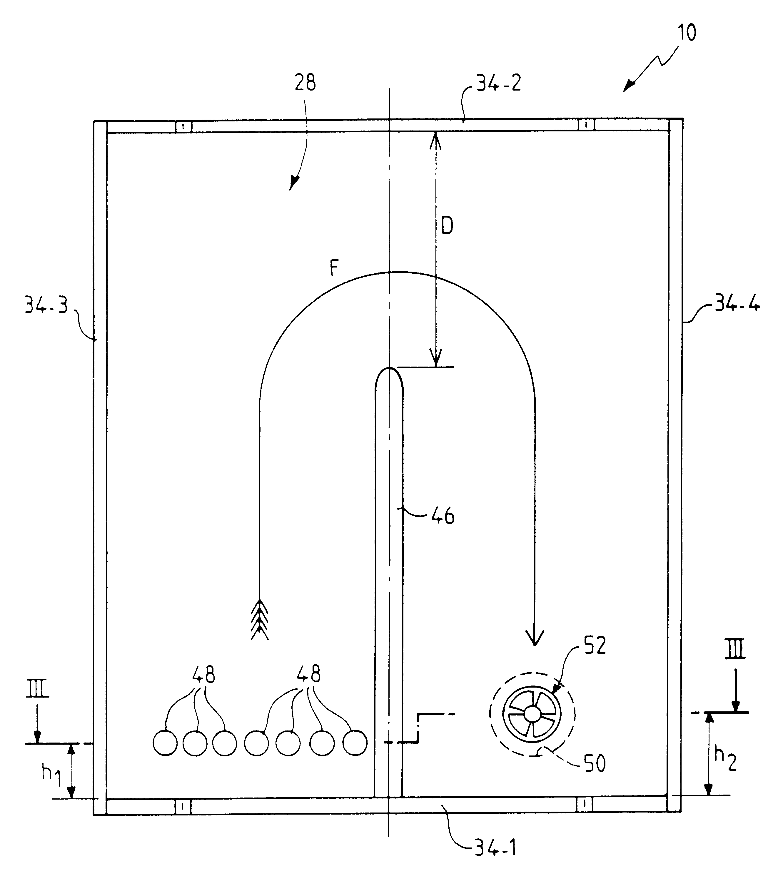
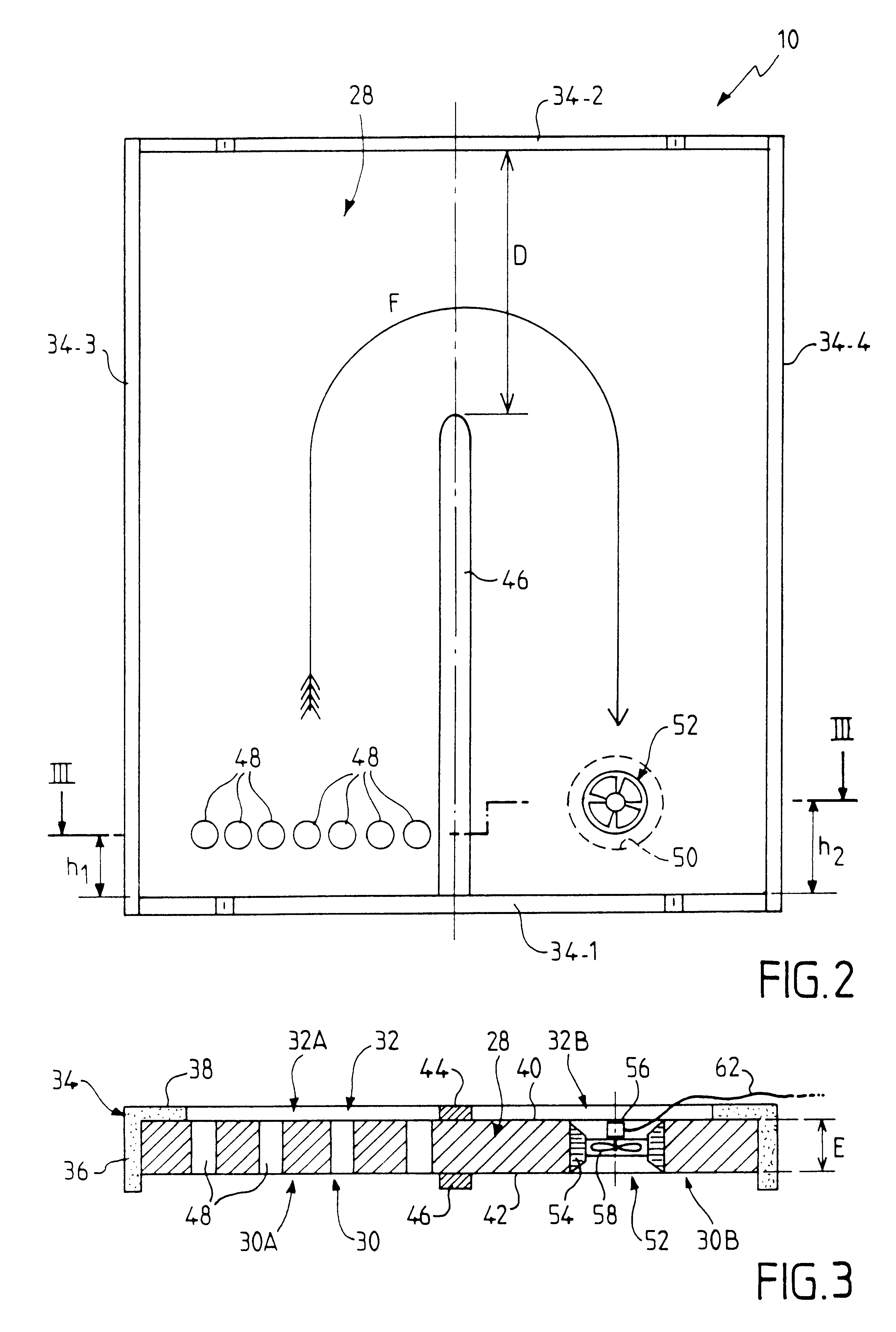
This arrangement of U-shaped circuits consists essentially of vertical walls. It ensures good scouring of the surfaces and facilitates the circulation of the air in each of the external and internal spaces, as well as a circulation of the air from one to the other. An effect analogous to scouring could be obtained by other means, for example by bends or diversions, or even by other types of circuit for circulating air between the two above-mentioned spaces.
With this in mind, the invention provides means for protection against the occurrence of excessive temperatures.

Problems solved by technology

In practice it has been found that a single opening allows only very limited exchange of air.
When insolation is present and the transfer of heat to the wall surface is closed off, the temperature could attain levels which, for certain materials, in particular insulation, are excessive.

Method used


Image

  • Device for transferring heat between a panel heated by solar radiation and a wall
  • Device for transferring heat between a panel heated by solar radiation and a wall
  • Device for transferring heat between a panel heated by solar radiation and a wall

Examples


Embodiment Construction

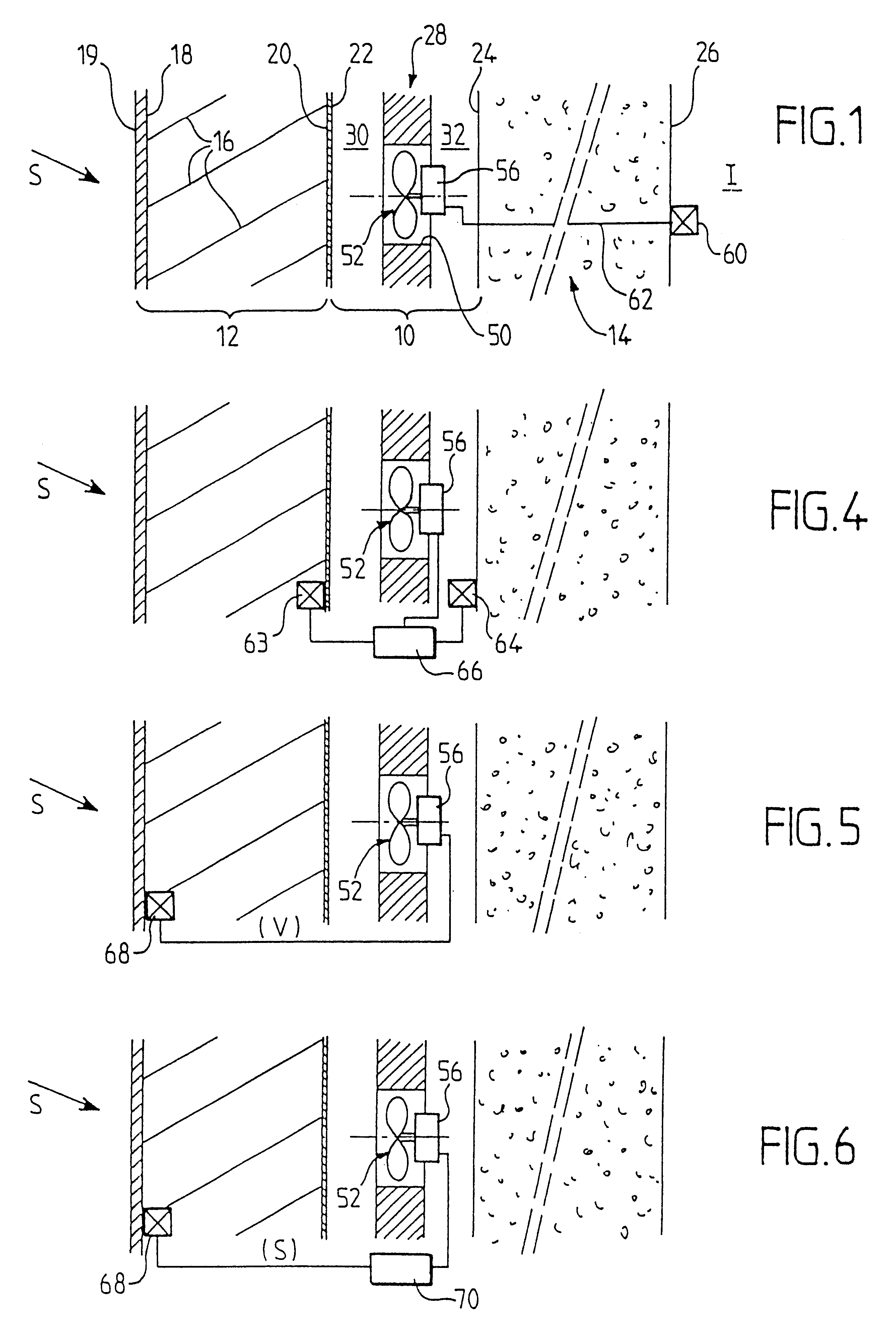
We refer first to FIG. 1 which shows a heat transfer device 10 according to the invention, mounted between a panel 12 designed to be heated by solar radiation S and a wall surface 14 which constitutes the wall of a building. The panel 12, also known as a "solar panel" or "transparent insulation" is, in this example, realized in accordance with the teaching of French Patent No. 92 03962. It will be understood that this panel could take another form, of a kind, which allows the capture of solar energy.

In the example the panel 12 comprises a number of substantially horizontal identically-shaped elements 16 spaced from one another, and superposed in a substantially vertical plane to form a kind of curtain. This curtain has an external face 18 and an internal face 20. The external face 18 is closed by a transparent plate 19 (for example a sheet of glass) designed to be exposed to solar radiation S. The internal face 20 is closed by a plate 22 such as a metal sheet colored black.

The plate...


PUM


Abstract

A device for transferring heat between a panel heated by solar radiation and a wall surface, including an insulating plate mounted parallel between the panel and the wall surface, to define a closed external space between the panel and the insulating plate, and a closed internal space between the insulating plate and the wall. An air circulator is interposed between the external space and the internal space and can be put selectively in an open state allowing circulation of air between the external space and the internal space, and thus allowing thermal transfer between the panel and the wall, and a closed state preventing circulation of air between the external space and the internal space, and thus preventing thermal transfer between the panel and the wall.

Description

1. Field of the InventionThe invention relates to a device for transferring heat between a panel designed to be heated by solar radiation and a wall, such as for example the wall of a building.2. Description of the Related ArtThere are already known arrangements applied to the face of a building for capturing solar energy and heating a receiving medium such as, for example, an outside wall of the building or a volume of air inside the building.These arrangements for capturing solar energy are sometimes also called "solar panels" or "transparent insulation".An arrangement of this type is described for example in French Patent No. 92 03962.This known device comprises a number of substantially horizontal shaped elements spaced apart and superposed to form a curtain having an external face designed to be exposed to solar radiation and an internal face designed to be arranged facing the receiving medium which is to be heated. This device thus permits the transfer of the heat while at the...

Claims


Application Information

Patent Timeline
Patent Type & Authority Patents(United States)
IPC IPC(8): F24J2/04F24J2/40
CPCF24J2/0444F24J2/402F24J2002/4605Y02B10/20Y02E10/44F24S50/40F24S20/66F24S2080/07Y02E10/40E04B1/74
Inventor RYLEWSKI, EUGENIUSZ
Owner RYLEWSKI EUGENIUSZ
Learn More