Retractable cord assembly

a technology of retractable cords and assemblies, which is applied in the direction of insulated conductors, cables, and relatively moving parts, etc., can solve the problems of compromising several individual conductors wrapped together, cords may eventually suffer failure, and one of its conductors may fail, so as to improve the resistance to failure

Inactive Publication Date: 2002-12-17
ASTRONICS CONNECTIVITY SYST & CERTIFICATION CORP
View PDF30 Cites 60 Cited by
  • Summary
  • Abstract
  • Description
  • Claims
  • Application Information

AI Technical Summary

Benefits of technology

It is an object of the invention to provide a multi-conductor cord that offers improved resistance to failure.

Problems solved by technology

Through use, including dispensing, retraction, bending and the like, these cords may eventually suffer failure.
Such cords typically compromise several individual conductors wrapped together.
As such a cord bends and rotates, one of its conductors may fail.
Upon the failure of a single conductor element, the entire cord is failed.
A frequent point of failure is at the point of connection between the retractable cord and the device.
In the case of a telephone, for instance, the point where the cord joins the phone is a frequent failure point.
These factors or increased wear at the device connection point often lead to premature failure.
Another frequent failure problem arises for applications that require the cord to travel through a conduit.
Frequent failures occur under such conditions.
One cause of failure is friction that develops between the cord and the conduit as the cord is pulled through the conduit.
This friction leads to accelerate wear on the cord through heating of the surface and increased stress on the cord.
Another cause of failure is through kinking or cracking of the conduit itself; particularly if it is required to move or otherwise flex.
Friction between the retractable cord and conduit can cause the outer surface of the cord to fray or otherwise deteriorate.
This increases friction between the cord and the conduit, making operation difficult.
Further, this friction increases the stress on the cord and connections, likewise leading to a shortened service life.
If the cord does not retract fully, as may be caused by excessive friction, the operator may improperly push or force the cord into the conduit, causing cord kinks, which may lead to failure.

Method used


Image

  • Retractable cord assembly
  • Retractable cord assembly
  • Retractable cord assembly

Examples


Embodiment Construction

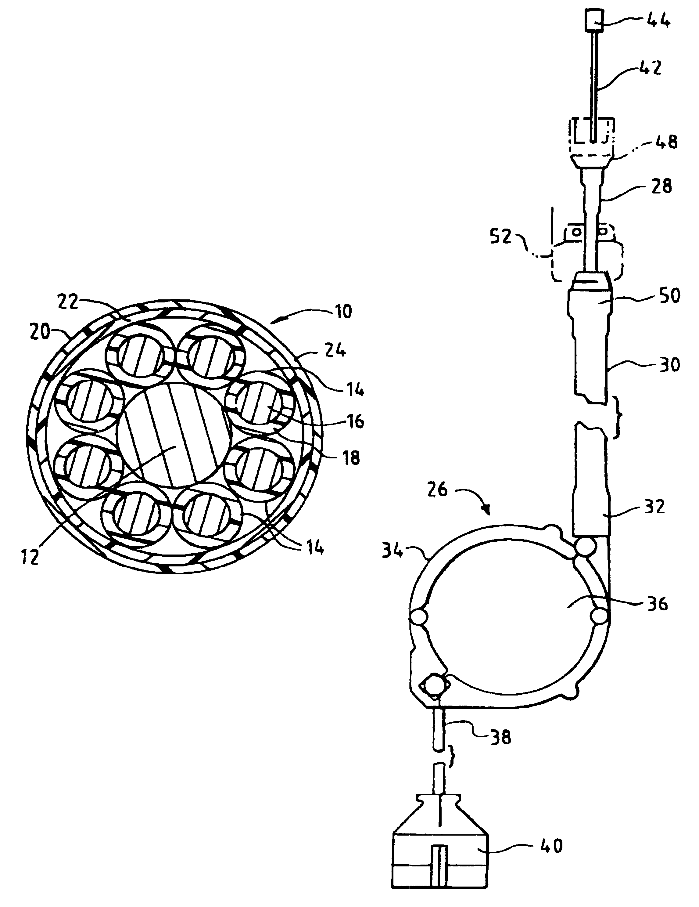
The present invention will be further described in reference to a preferred embodiment of a cord management system for a telephone and / or other electronic devices for use in aircraft. As will be appreciated by those skilled in the art, many other embodiments and commercial applications of the invention are possible.

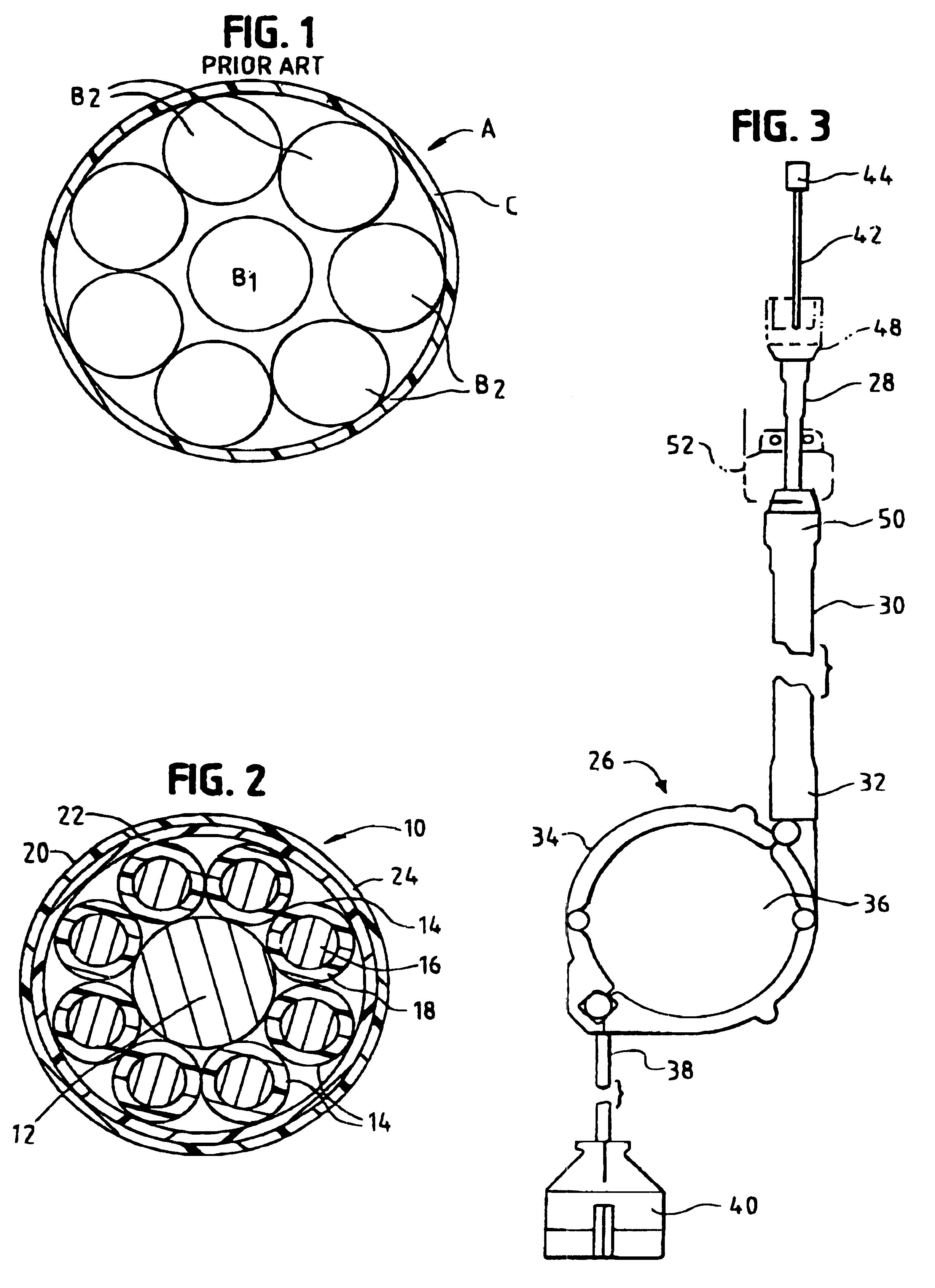
Referring now to FIG. 1, a prior art cable A is shown as comprising eight conductors B within an insulating jacket C. More specifically, the cable comprises a central conductor B.sub.1. The remainder of the conductors B.sub.2 are helically wound around the central conductor.

It has been discovered that cables that have a center conductor tend to have a short life when exposed to repeated tension and bending. As the cable is bent, the helical winding of the perimeter conductors evens out the tension that would normally result if the conductors were not wound. When a homogeneous material is exposed to bending, the outer fibers are exposed to tension, and the inner fibers are...


PUM

PropertyMeasurementUnit
diameteraaaaaaaaaa
elastomericaaaaaaaaaa
compressibleaaaaaaaaaa

Abstract

The retractable cord assembly (26) comprises a cable (28) having a central carrier and plural conductors helically wrapped about the central carrier. The assembly further includes a grommet for connecting the cable (28) to a device, the grommet having a head and stem, with a passage throught he head and stem for receiving the cable (28). The passgae is tapered to provide an enlarged proximal end when installed. The assembly further includes a flexible metal conduit (30) through which the cable slides. The cable outer surface is nylon braid and the conduit inner surface is a nickel plated to minimize friction therebetween.

Description

The present invention relates to retractable cord assemblies for use with telephones and other electrical or electronic devices.Cord reels are used to retract and dispense cords for electrical devices such as telephones. To be operable, the cord must conduct electrical signals. Also, in the case of a retractable cord and reel, the cord may be under retractive spring pressure. Through use, including dispensing, retraction, bending and the like, these cords may eventually suffer failure.Such cords typically compromise several individual conductors wrapped together. As such a cord bends and rotates, one of its conductors may fail. Upon the failure of a single conductor element, the entire cord is failed.A frequent point of failure is at the point of connection between the retractable cord and the device. In the case of a telephone, for instance, the point where the cord joins the phone is a frequent failure point. As the handset is moved about, the cord at this connection point is bent...

Claims


Application Information

Patent Timeline
Patent Type & Authority Patents(United States)
IPC IPC(8): H02G11/02H02G11/00
CPCH02G11/02
Inventor BURKE, PAUL C.SKOWRONSKI, RICHARD E.
Owner ASTRONICS CONNECTIVITY SYST & CERTIFICATION CORP
Why Eureka
Try Eureka