Cold cathode electron gun

a technology of cold cathode and electron gun, which is applied in the direction of discharge tube/lamp details, electric discharge tubes, travelling-wave tubes, etc., can solve the problem of inconsistent design procedures of conventional cold cathode electron gun

Inactive Publication Date: 2002-12-17
NEC CORP
View PDF10 Cites 6 Cited by
  • Summary
  • Abstract
  • Description
  • Claims
  • Application Information

AI Technical Summary

Problems solved by technology

However, the conventional designing procedures for the cold cathode electron gun are not consistent, because merely the

Method used


Image

  • Cold cathode electron gun
  • Cold cathode electron gun
  • Cold cathode electron gun

Examples


Embodiment Construction

Modes of embodiment of the present invention are explained, referring to the drawings.

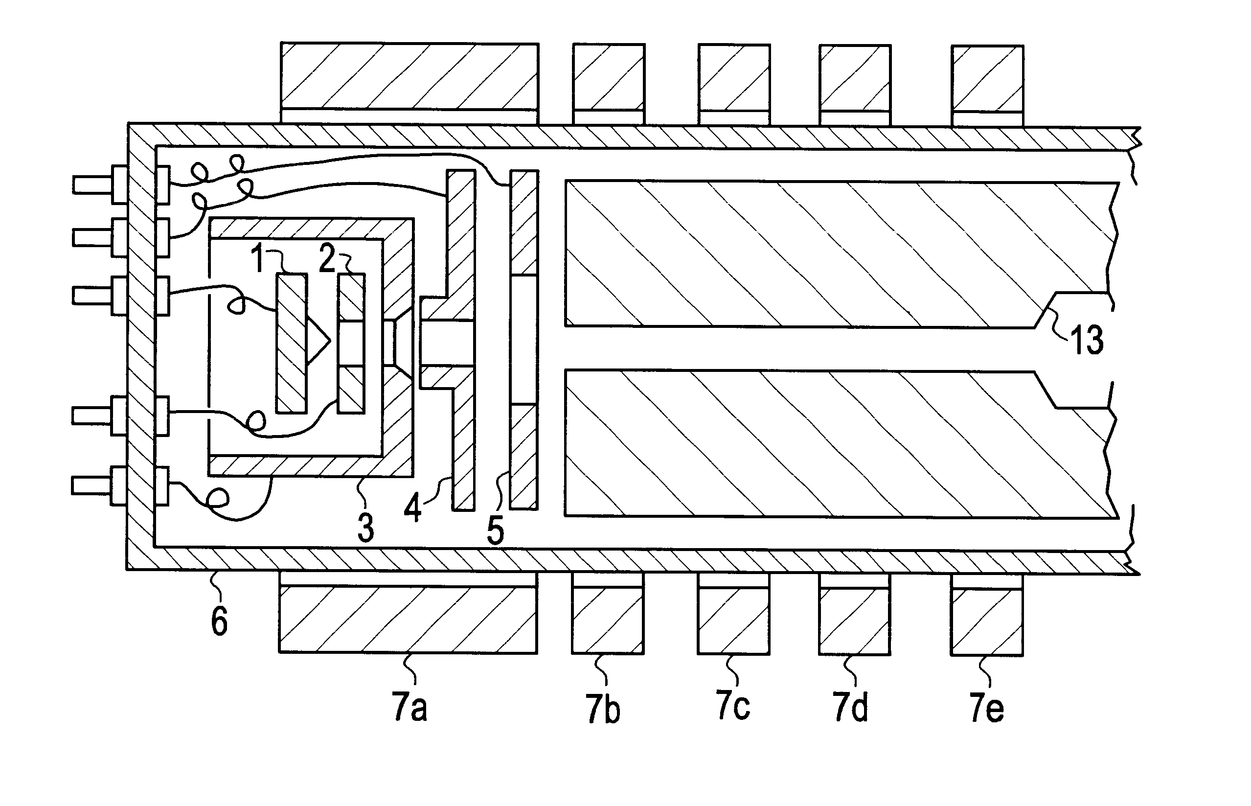
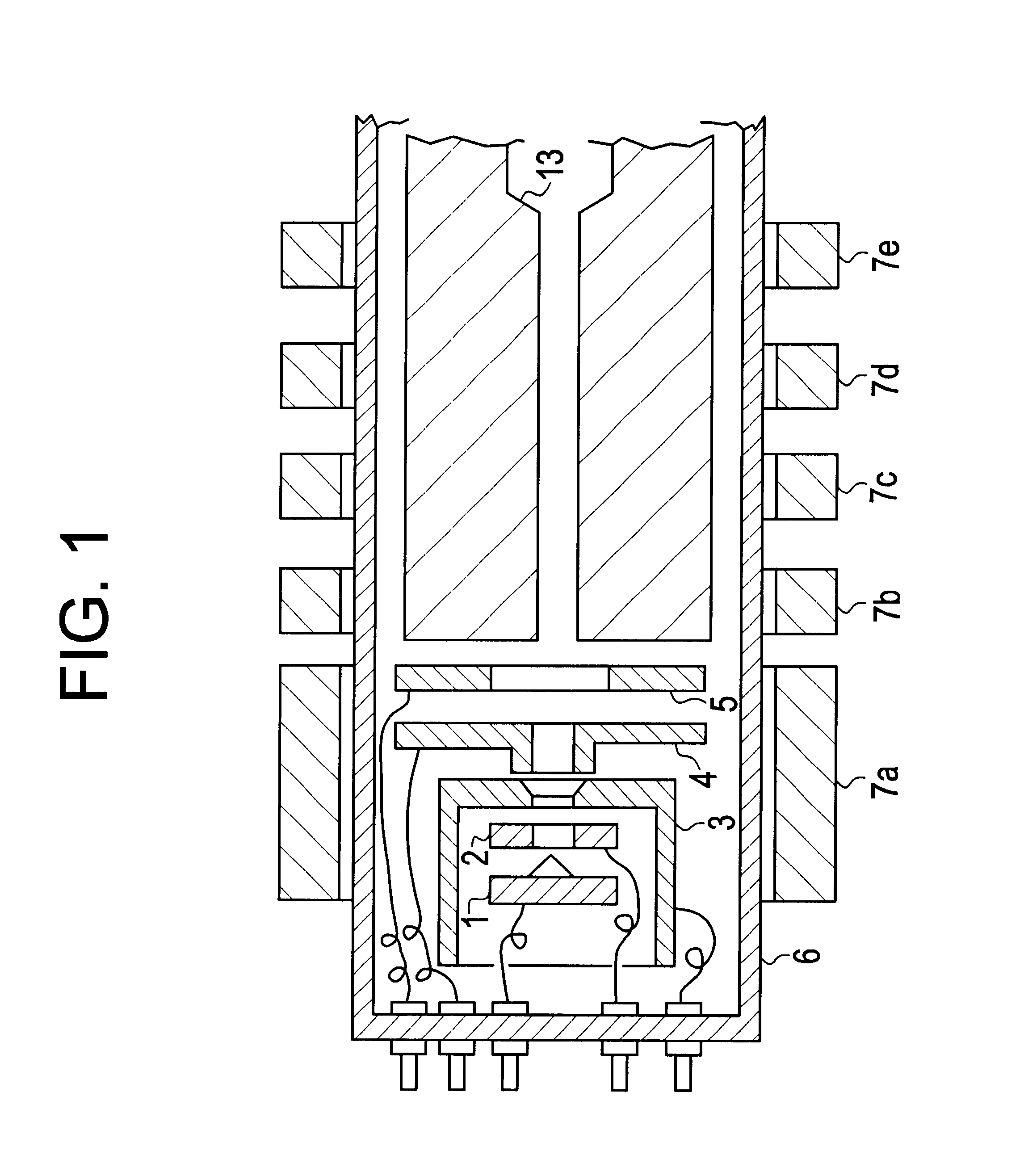
A cross sectional view of the cold cathode electron gun of the present invention is shown in FIG. 1. As shown in FIG. 1, the cold cathode electron gun of the present invention comprises cold cathode 1 for emitting electrons by the field-emission, gate electrode 2 for controlling the field-emission, Wehnelt electrode which surrounds cold cathode 1 and gate electrode 2, first anode 4 for accelerating the electrons, second anode 5 which constructs an electron lens together with first anode 4. This electron gun is contained in vacuum envelope 6 of, for example, a traveling wave tube. Further, a plurality of magnets 7a, 7b, 7c, 7d, 7e are arranged around a slow wave circuit.

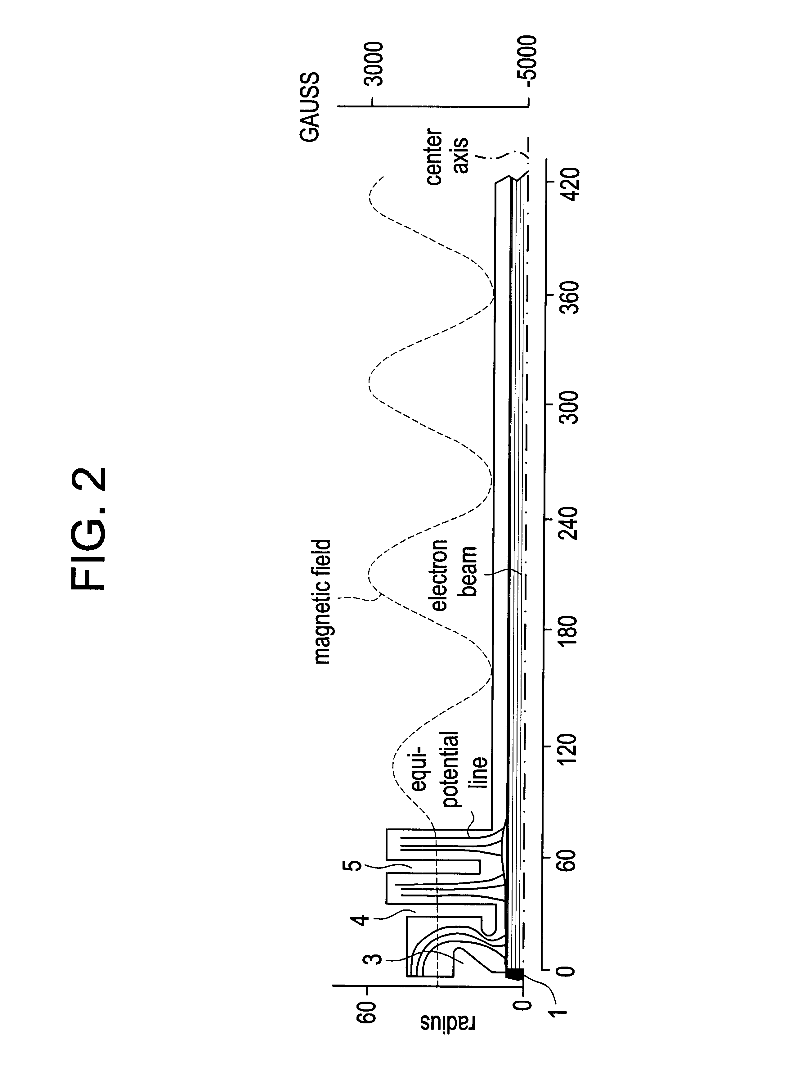
The divergence angle of the electron beam emitted from the cold cathode is 25.degree. to 30.degree. as mentioned above. Further, according to the inventor's experiment, 97.5% of the total current is contained in this divergence angle...


PUM


Abstract

To stabilize an emission current of cold cathode electron gun and extend its product life. A cold cathode electron gun comprises a cold cathode for emitting electrons by field-emission, a gate electrode for controlling the field-emission, a Wehnelt electrode which surrounds the cold cathode and the gate electrode, a first anode for accelerating electrons, and a second anode for constructing an electron lens together with the first anode. An inner diameter of the first anode is greater than a radius of flow of electrons which are emitted in the direction perpendicular to the optical axis of the electron lens.

Description

1. Field of the InventionThe present invention relates to a cold cathode electron gun, such as a field emitter array, which can supply a stable electron flow for a long time period by avoiding collisions of electrons against an inner wall of anode.2. Description of the Prior ArtSo far, designing methods concerning hot cathode electron gun have been applied also for designing structures of anode of cold cathode electron guns.For example, in case of a traveling wave tube, a value of electron current, a radius of electron beam in a slow wave circuit, an inner diameter of helix, a pitch of the helix must be decided on the basis of a product specification such as operating frequency and output power. The radius of electron beam, for example, is set to be about 60% of the inner diameter of helix, taking into consideration manufacturing factors such as a degree of off-axis between the electron lens and the slow wave circuit, and a distortion and curvature of the helix.In the hot cathode el...

Claims


Application Information

Patent Timeline
IPC IPC(8): H01J23/02H01J3/02H01J23/065H01J3/00H01J1/304H01J23/06
CPCH01J3/021H01J23/065
Inventor IMURA, HIRONORI
Owner NEC CORP
Why Eureka
Try Eureka