Telecommunications system power supply

a technology of telecommunications system and power supply, which is applied in the direction of optical elements, manufacturing tools, instruments, etc., can solve the problems of limited power which can be fed to underwater repeaters such as optical amplifiers or regenerators, and the growth of the capacity of terrestrial systems. it is possible to increase the length of the cable, increase the data carrying capacity, and increase the power.

Inactive Publication Date: 2002-12-17
RPX CLEARINGHOUSE
View PDF10 Cites 33 Cited by
  • Summary
  • Abstract
  • Description
  • Claims
  • Application Information

AI Technical Summary

Benefits of technology

Several advantages can arise from providing a separate cable for some or all of the power supply. Firstly it enables the routing of the cable for data traffic and of the second cable for power supply, to be independently optimised. In particular the power route may be made shorter or multiple power feeds used. This enables more power to be delivered to the repeaters, which enables more repeaters, more functionality in the repeaters, and more fibre pairs. More functionality in each repeater can enable more capacity (through more channels and / or higher data rates per channel).
Another preferred example has a tail for coupling the power from the second cable to the repeaters of the first cable, the second cable and the first cable each having a branch to couple the tail. This is a preferred alternative to a four way junction box because it keeps the cables more independent, which may ease installation and upgrading, and because branching technology is tried and tested.

Problems solved by technology

Underwater systems have not matched the growth in capacity of such terrestrial systems.
The two primary reasons are the limitation in the amount of power which can be fed to underwater repeaters, such as optical amplifiers or regenerators, and the extremely high reliability requirements for such underwater equipment.
The reliability is required because the underwater equipment is so inaccessible for maintenance or repair, once installed.
Notably, these components may be amongst the least reliable, depending on the pump power level and other factors.
If the losses in the copper are reduced by using thicker copper, the weight of the cable increases prohibitively.
If more repeaters are added, the total voltage drop increases, and the insulation of the cable and the repeaters, to withstand such high voltages, becomes prohibitively heavy.
For these reasons, often only 8 to 12 fibre pairs are installed in the cable, because it is impossible to supply more power for sufficient optical amplifiers for more fibres.

Method used


Image

  • Telecommunications system power supply
  • Telecommunications system power supply
  • Telecommunications system power supply

Examples


Embodiment Construction

Embodiments of the invention will now be described in more detail. They illustrate the invention by way of example, and the scope of the invention is not limited to these examples.
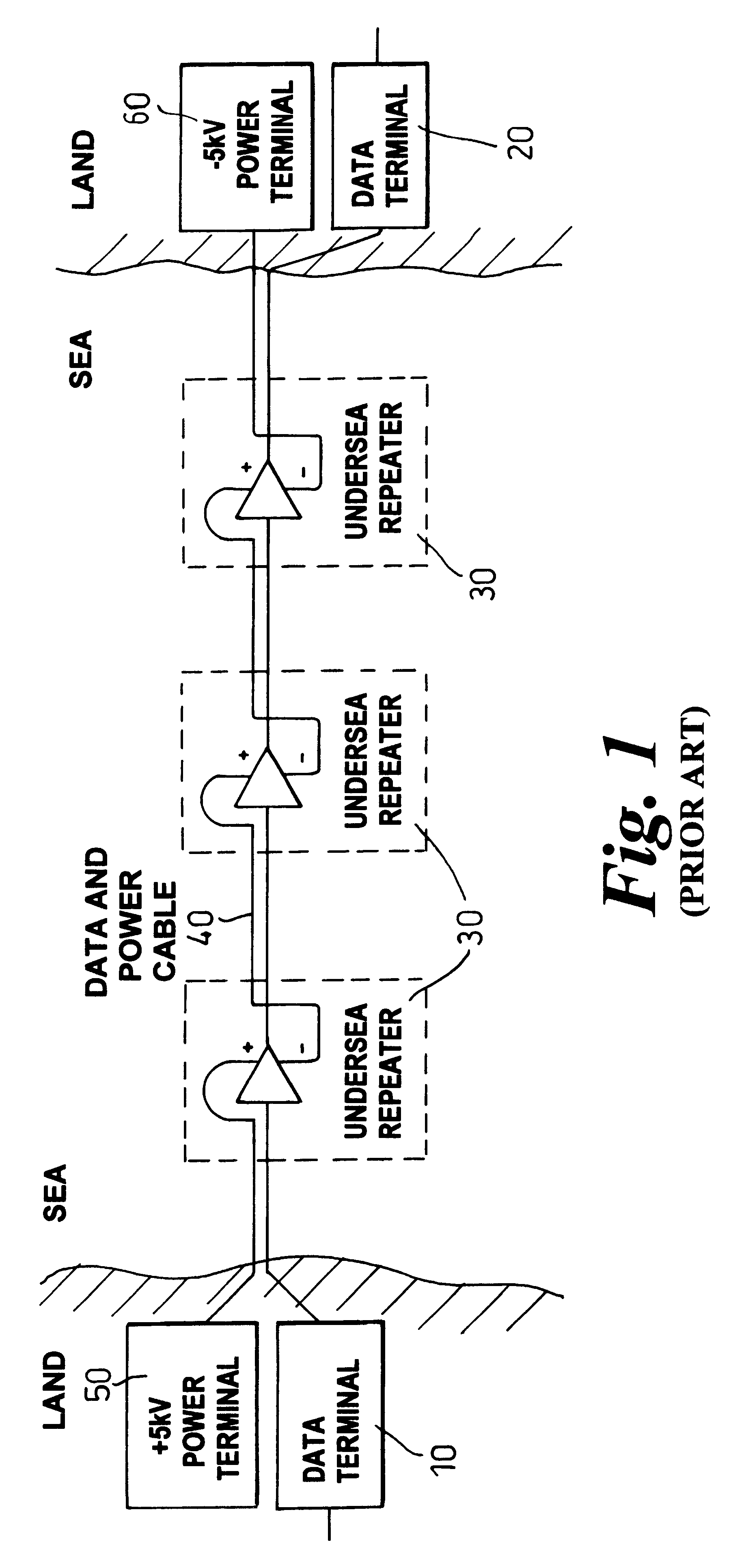
FIG. 1

FIG. 1 shows a prior art under sea data transmission system in which data is sent from a first data terminal 10 to a second data terminal 20, via under sea repeaters 30. Such repeaters require a power supply. Accordingly, such a system is known as a powered system. Electric power is fed from the same cable 40, as is used by the data. The repeaters are connected in series along the cable. A proportion of the voltage is dropped by each repeater, and in a typical case where the cable stretches for 50-100 kilometers between repeaters, a considerable proportion of the voltage is dropped by losses in the cable.

Accordingly, at power terminals 50, 60 at each end of the cable, a voltage source of several thousand volts is required. This is usually a DC supply, which may be converted from a local terrestrial A...


PUM

PropertyMeasurementUnit
voltageaaaaaaaaaa
power supplyaaaaaaaaaa
poweraaaaaaaaaa

Abstract

An underwater telecommunications system has a first underwater cable for carrying data traffic, one or more underwater repeaters, and an underwater power network for supplying power to the repeaters. By providing a separate cable for some or all of the power supply, the power route may be made shorter, thus more power can be delivered, therefore more repeaters can be used, which enables more fiber pairs to be laid, and thus the capacity to be increased.

Description

The invention relates to underwater telecommunications systems, underwater power networks for supplying power to underwater equipment, to underwater repeaters, to methods of installing such apparatus, and to methods of upgrading such apparatus.BACKGROUND TO THE INVENTIONIt is known to provide telecommunications systems having equipment underwater for various purposes.One application is for data transmission between land sites separated by water. Other applications include telemetry or monitoring of underwater installations for other purposes. Conventional underwater data transmission systems started with metallic conductors arranged in a coaxial cable. Fibre optic transmission systems were later introduced. For spans beyond several hundred kilometers, repeaters were required. These started with optical to electrical to optical regenerators. In the 1990's, optical amplifier systems were introduced, to avoid the conversion into the electrical domain.In corresponding terrestrial optica...

Claims


Application Information

Patent Timeline
Patent Type & Authority Patents(United States)
IPC IPC(8): H02G15/10H02G15/14
CPCH02G15/14
Inventor SPAGNOLETTI, ROBERTFELLS, JULIANHARDCASTLE, IANADAMS, GARRY
Owner RPX CLEARINGHOUSE
Why Eureka
Try Eureka