Hydrodynamic coupling device

Inactive Publication Date: 2002-12-24
ZF FRIEDRICHSHAFEN AG
View PDF5 Cites 22 Cited by
  • Summary
  • Abstract
  • Description
  • Claims
  • Application Information

AI Technical Summary

Problems solved by technology

However, the problem with this arrangement is that the working fluid flowing in

Method used


Image

  • Hydrodynamic coupling device
  • Hydrodynamic coupling device
  • Hydrodynamic coupling device

Examples


Embodiment Construction

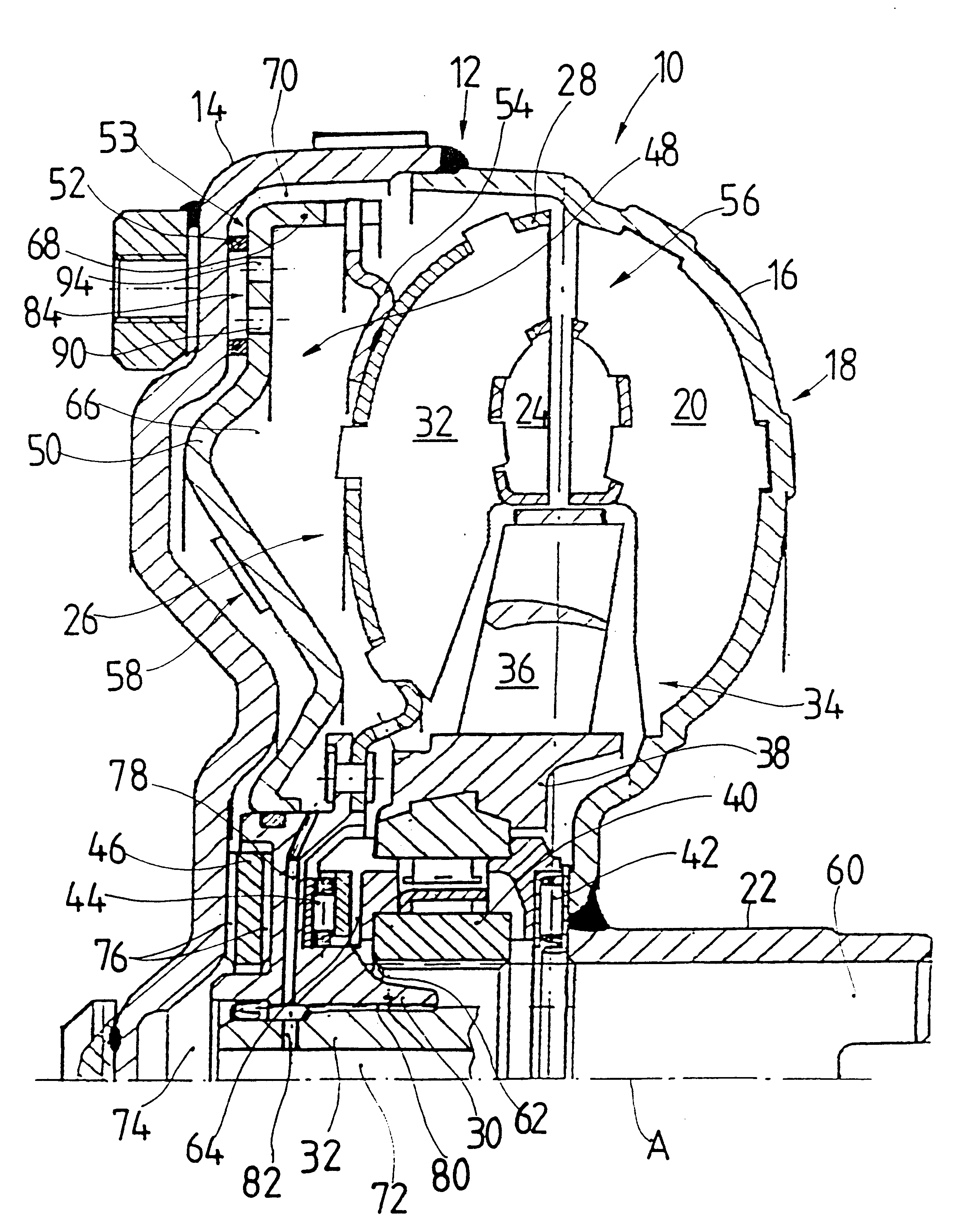
FIG. 1 illustrates the present invention in the form of a hydrodynamic torque converter. The torque converter 10 comprises a housing, designated as a whole by 12, which comprises a housing cover 14 and a pump impeller shell 16 of a pump impeller 18, with the shell being fixedly connected to the housing cover 14 radially on the outside, for example by welding. The pump impeller shell 16 carries, on its inside, a plurality of pump impeller blades 20 succeeding one another in the circumferential direction. The pump impeller shell 16 is connected fixedly, radially on the inside, to a pump impeller hub 22 which may, for example, drive a fluid pump arranged in a gear.

Arranged in the interior 24 of the torque converter 10 is a turbine wheel, designated as a whole by 26, which comprises a turbine wheel shell 28, a turbine wheel hub 30 connected fixedly to the latter and a plurality of turbine wheel blades 32 succeeding one another in the circumferential direction on the turbine wheel shell ...


PUM


Abstract

A hydrodynamic coupling device is provided including a housing, a lock up clutch, a friction surface mechanism, a fluid duct and three connecting ducts. The lock up clutch has a clutch element arranged in the housing and may be pressed against the housing. The friction surface mechanism is arranged between the clutch element and the housing. The clutch element and the friction surface mechanism separate an interior of the hydrodynamic coupling device into a first fluid space and a second fluid space. The fluid duct means is in the friction surface mechanism and permits the working fluid to flow into and out of the first fluid space while preventing the working fluid from flowing out of the first fluid space into the second fluid space. The connecting ducts are in the fluid duct, with the first connecting duct is capable of permitting flow of the working fluid to the first fluid space, the second connecting duct is capable of permitting flow of the working fluid into and out of the second fluid space. The third connecting duct is capable of circulating the working fluid within the first fluid space before permitting the working fluid to flow out of the first fluid space, at least when the clutch element is pressed up to the housing with the friction surface arrangement interposed between them.

Description

1. Field of the InventionThe present invention relates to a hydrodynamic coupling device, in particular a torque converter. The interior of the hydrodynamic coupling device may be separated into a first fluid space and a second fluid space by means of a clutch element comprising a lockup clutch and a friction surface arrangement. The clutch element is capable of being pressed up to a housing or a component connected to the housing, with the friction surface arrangement interposed. In the friction surface arrangement is a fluid duct arrangement, into which working fluid can flow from the first fluid space and out of which working fluid can flow only toward the first fluid space. Working fluid is supplied to the first fluid space by means of a first connecting duct arrangement and working fluid is led into and / or out of the second fluid space by means of a second connecting duct arrangement.2. Description of the Related ArtA hydrodynamic coupling device is known from EP 0 428 248 A1. ...

Claims


Application Information

Patent Timeline
IPC IPC(8): F16H45/02F16H45/00
CPCF16H45/02F16H2045/0215F16H2045/0289F16H2045/0294
Inventor SASSE, CHRISTOPHILLIG, ROLANDMOHR, RAINER
Owner ZF FRIEDRICHSHAFEN AG
Why Eureka
Try Eureka