Lens periphery edge processing apparatus

a processing apparatus and periphery technology, applied in the direction of grinding drives, lapping machines, manufacturing tools, etc., can solve the problems of considerable time and complicated operation for inserting or detaching the reference glob

Inactive Publication Date: 2002-12-24
KK TOPCON
View PDF6 Cites 20 Cited by
  • Summary
  • Abstract
  • Description
  • Claims
  • Application Information

AI Technical Summary

Problems solved by technology

Accordingly, there are problems that the operation for inserting or detaching the reference globe is complicated, and considerable time is required.

Method used


Image

  • Lens periphery edge processing apparatus
  • Lens periphery edge processing apparatus
  • Lens periphery edge processing apparatus

Examples


Embodiment Construction

Hereinafter, the embodiments of the present invention will be explained with reference to the accompanying drawings.

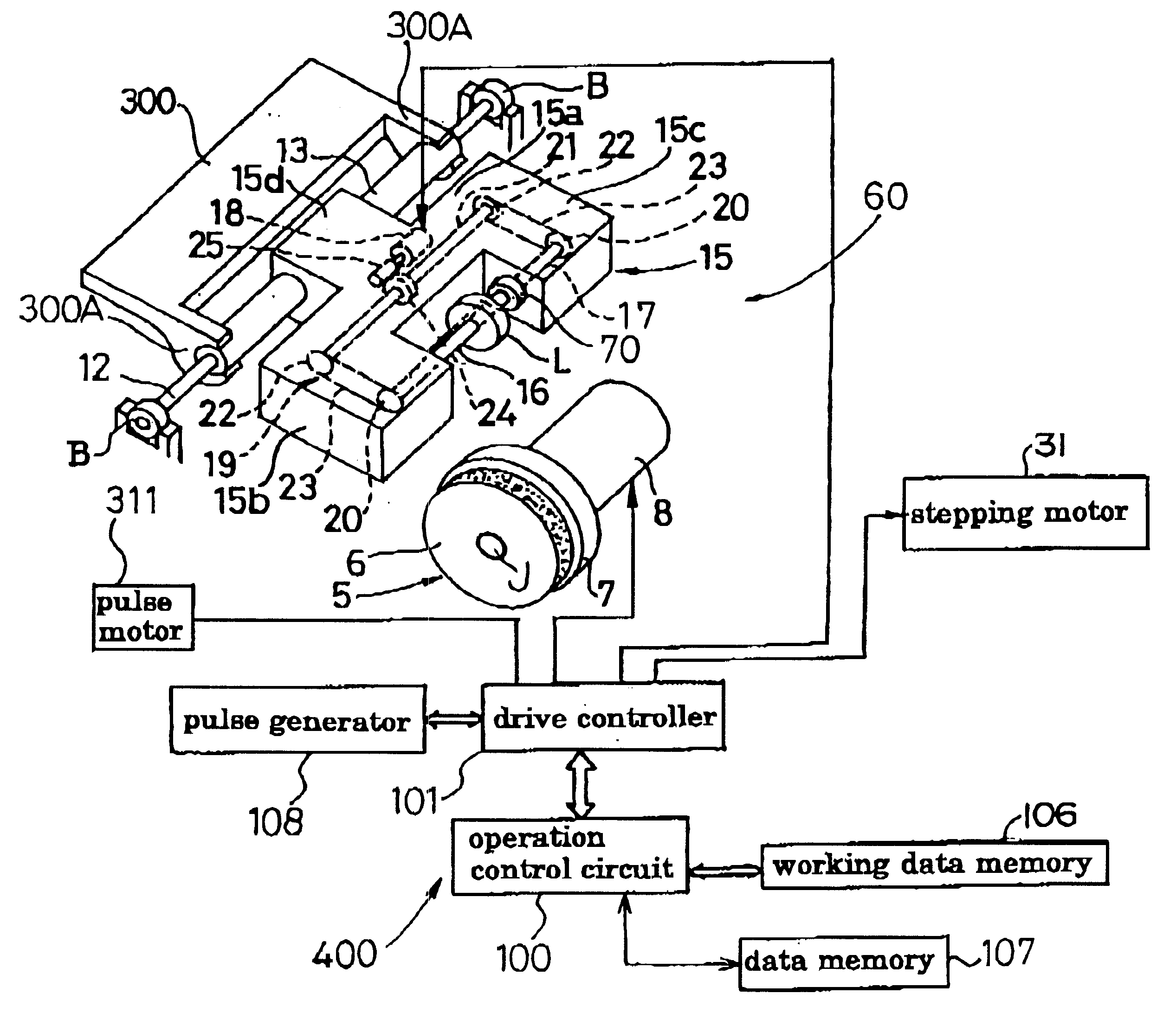
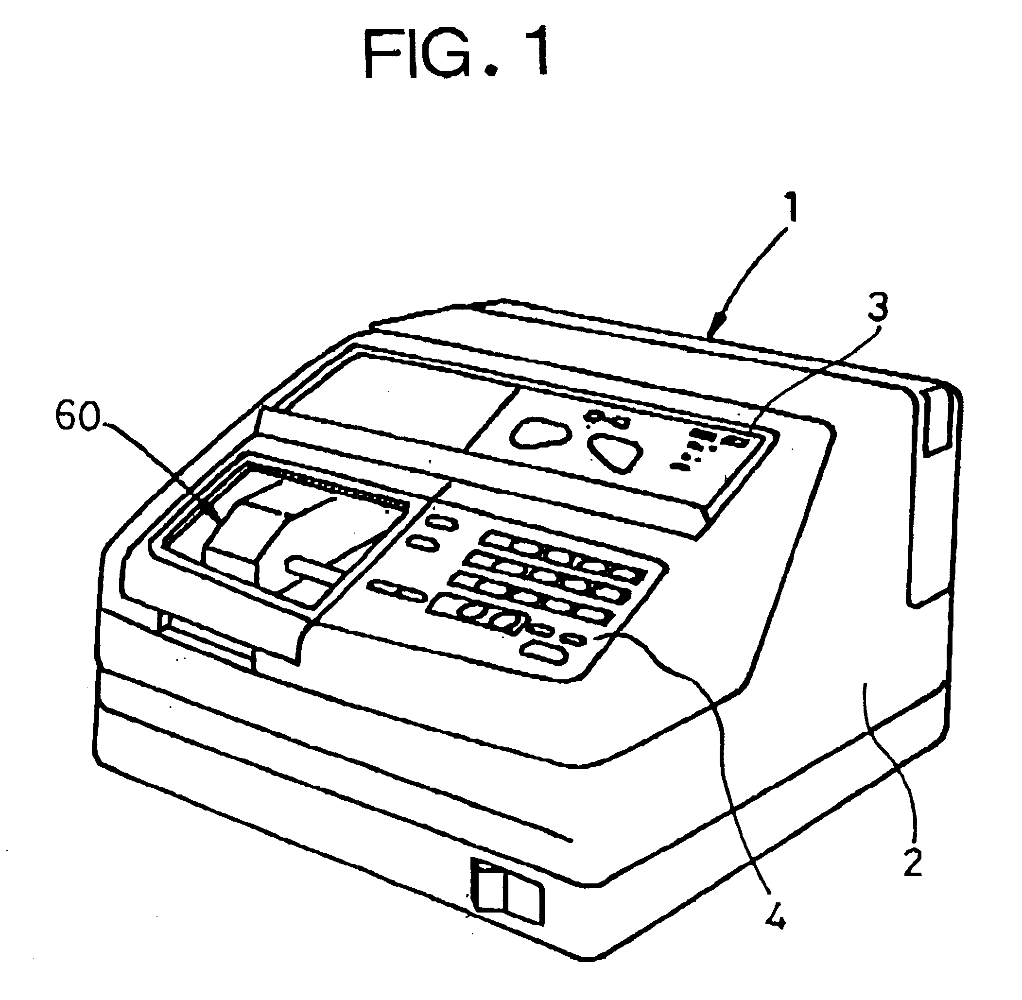
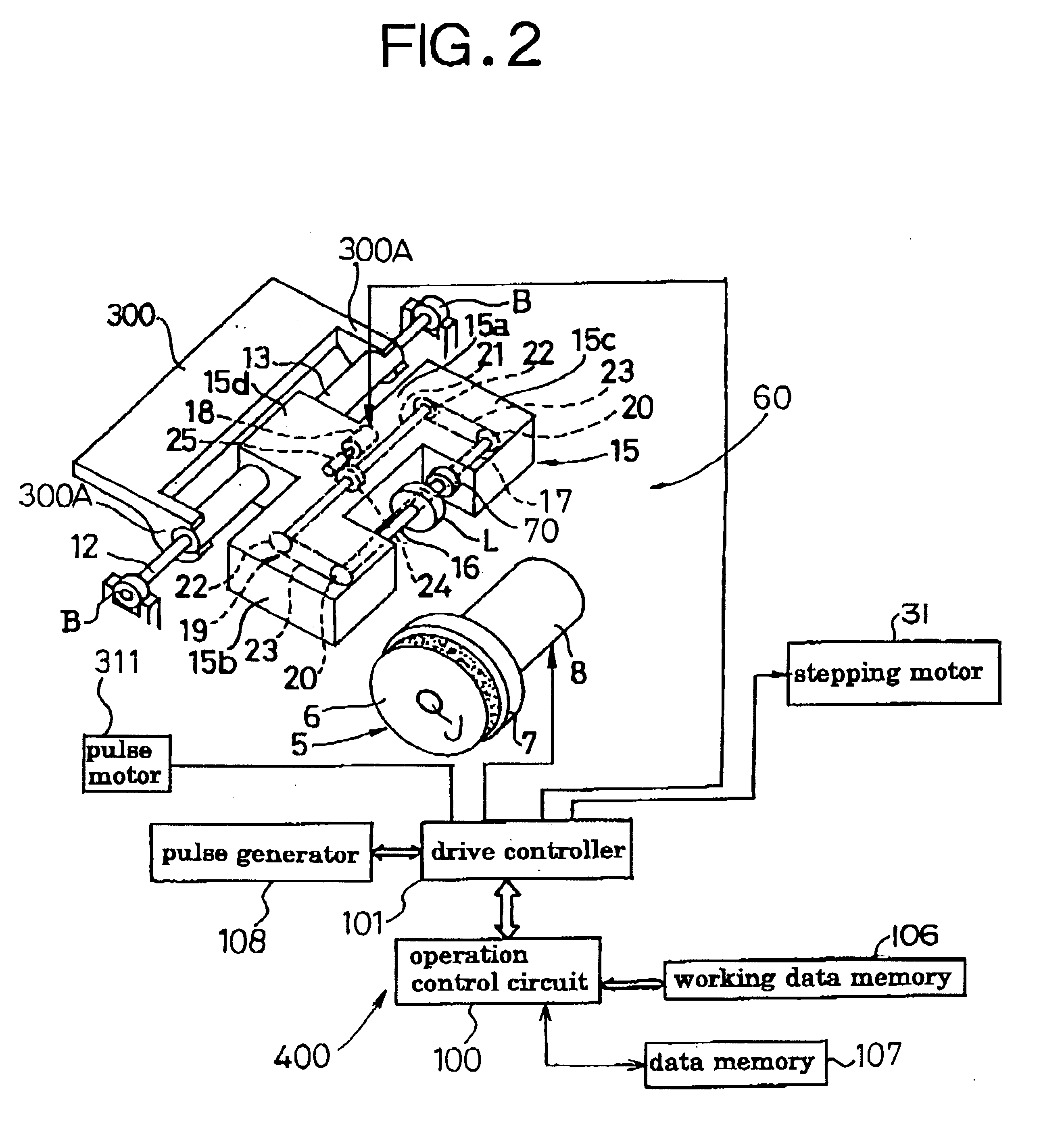
As shown in FIGS. 1 and 2, the lens periphery edge processing apparatus 1 comprises a body 2, and a grinding portion 60 provided in the body 2.

In the slanted surface of the body 2, a liquid crystal display portion 3 and a keyboard portion 4 are provided.

The grinding portion 60 has a grindstone 5 rotated by a motor 8, a carriage 15 rotatable around a supporting shaft 12, and a pair of lens rotating shafts 16, 17 supported by the carriage 15. The grindstone 5 comprises a rough grindstone 6 and a V-shaped groove grindstone 7, and is rotated around an axis of grindstone rotating shaft J.

The carriage 15 has a carriage body 15a, arm portions 15b, 15c which are integrally provided in the both sides of the carriage body 15a toward the front side and are parallel with each other, and a protrusion portion 15d protruded toward the rear side in the center of the rear edge of the c...


PUM

PropertyMeasurementUnit
rotated angleaaaaaaaaaa
angleaaaaaaaaaa
shapeaaaaaaaaaa

Abstract

In a lens periphery edge processing apparatus comprising lens rotating shafts 16, 17 for putting and holding an objective lens therebetween, a carriage 15 rotatable around a pivot, and a grindstone rotating shaft 9 provided with a grindstone 5 for grinding the objective lens L, the lens rotating shaft 17 is provided with a reference globe 70 having a predetermined radius.

Description

1. Field of the InventionThe present invention relates to a lens periphery edge processing apparatus for grinding a periphery edge of an objective lens to a lens shape such as a lens frame shape or mold shape of eyeglasses.2. Description of the Prior ArtIn conventional lens periphery edge processing apparatus, a reference globe is put and held between a lens rotating shafts instead of an objective lens, a carriage supporting the lens rotating shafts is lowered so that the reference globe is contacted with a grindstone, the location of the carriage at this time is detected, corrected data of the inter-shaft distance between a grindstone rotating shaft and the lens rotating shafts are obtained on the basis of the detected location data, and then, the reference globe is detached and the objective lens is put and held between the lens rotating shafts, the inter-shaft distance is corrected on the basis of said corrected data, and the vertical movement of the carriage is controlled, there...

Claims


Application Information

Patent Timeline
Patent Type & Authority Patents(United States)
IPC IPC(8): B24B47/22B24B47/00B24B9/14B24B9/06
CPCB24B9/146B24B37/013B24B47/22
Inventor KOBAYASHI, AKIOTAKAHASHI, YUMIKOIZUMI, HIROSHIABE, KAZUOTAYA, MAKOTONAKANISHI, MICHIKOSAITO, SUSUMU
Owner KK TOPCON
Why Eureka
Try Eureka