Double-side grinding apparatus for wafer and double-side grinding method

Active Publication Date: 2010-06-10
SUMCO TECHXIV
View PDF6 Cites 14 Cited by
  • Summary
  • Abstract
  • Description
  • Claims
  • Application Information

AI Technical Summary

Benefits of technology

[0016]As described above, the hydrostatic pad members facing a wafer are made of a ceramic material, so that deformation of the hydrostatic pad members due to thermal expansion can be restrained. In other words, even if the temperature of the hydrostatic pad members rises due to the heat generated during the grinding, deformation of the hydrostatic pad members through thermal expansion can be restrained. As a result, the nanotopography in the wafer surfaces after the grinding can be reduced. Also, even if the temperature of the hydrostatic pad members rises due to the heat generated during the grinding, a temperature rise in the hydrostatic pad members can be restrained, because the heat is conducted from the hydrostatic pad members to the base members face-bonded to the back surfaces of the hydrostatic pad members. Accordingly, deformation of the hydrostatic pad members through thermal expansion can be further restrained. As a result, the nanotopography in the wafer surfaces after the grinding can be reduced. Also, to achieve target wafer flatness, the flatness of the wafer facing sur

Problems solved by technology

In grinding a wafer, unevenness of the wafer surfaces after the grinding often becomes a problem, because trouble such as circuit disconnection is caused at the time of formation of a semiconductor circuit for the wafer.
As a result, the wafer facing surface of each hydrostatic pad member is deformed, and the static pressure cannot be distributed evenly onto the entire surface of the wafer.
Therefore, a reduction of nanotopography cannot be expected.
As a result, the spaces between the wafer and the hydrostatic pad members become uneven due to thermal expansion and contraction or slight deformation of each of the hydrosta

Method used


Image

  • Double-side grinding apparatus for wafer and double-side grinding method
  • Double-side grinding apparatus for wafer and double-side grinding method
  • Double-side grinding apparatus for wafer and double-side grinding method

Examples


Embodiment Construction

[0024]The following is a description of an embodiment of a double-side grinding apparatus for wafers according to the present invention, with reference to the accompanying drawings. The following embodiment is merely an example of the present invention, and various other structures may be used within the technical scope of the invention.

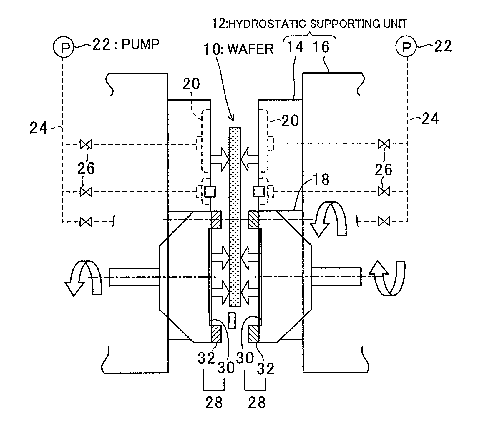
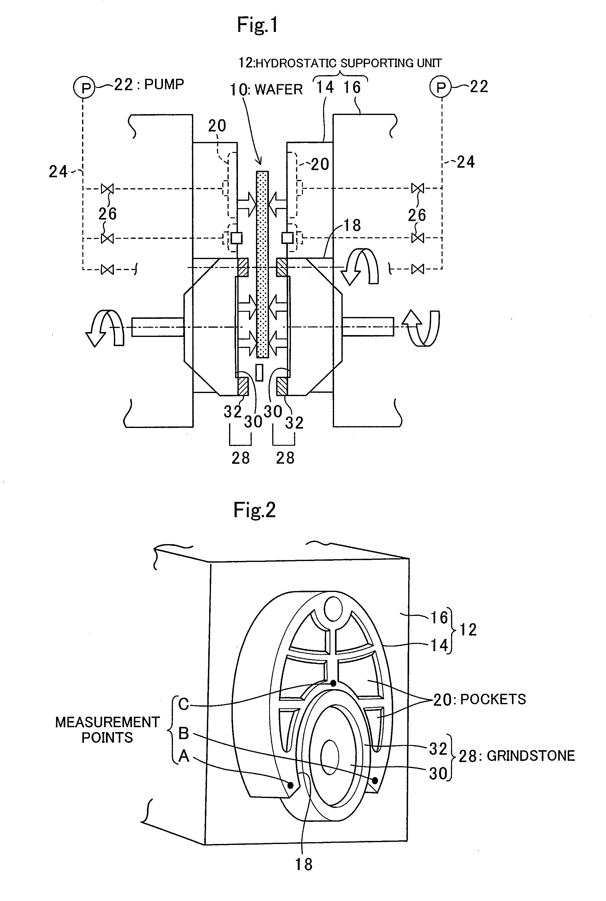
[0025]FIG. 1 is a cross-sectional view schematically showing the components of the hydrostatic supporting unit and the components surrounding the hydrostatic supporting unit in a double-side grinding apparatus for wafers according to the embodiment. FIG. 2 is a perspective view of the hydrostatic supporting unit shown in the upper left part of FIG. 1. As shown in FIG. 1, the double-side grinding apparatus of this embodiment has a wafer 10 to be ground at its center portion, and a pair of hydrostatic supporting units 12 at both side portions. Each of the hydrostatic supporting units 12 is formed with a hydrostatic pad member 14 directly facing the waf...


PUM

PropertyMeasurementUnit
Temperatureaaaaaaaaaa
Lengthaaaaaaaaaa
Thermal expansion coefficientaaaaaaaaaa

Abstract

A double-side grinding apparatus is designed to be capable of minimizing thermal expansion of hydrostatic pad members and reducing nanotopography in performing wafer grinding. The double-side grinding apparatus is a double-side grinding apparatus for wafers that can simultaneously grind either surface of a wafer to be ground by pressing a grindstone against either surface of the wafer to be ground while hydrostatically supporting either surface of the wafer to be ground in a noncontact manner. Each hydrostatic supporting unit is formed with a hydrostatic pad member facing the wafer to be ground, and a base member placed on the back surface of the hydrostatic pad member. The hydrostatic pad member is made of a ceramic member, and the base member is made of a metal member.

Description

BACKGROUND[0001](a) Field of the Invention[0002]The present invention relates to a grinding apparatus and a grinding method for wafers, and more particularly, to a double-side grinding apparatus and a double-side grinding method by which hydrostatic supporting units are placed on either surface side of a semiconductor wafer, and a fluid is supplied to spaces between the wafer and the hydrostatic supporting units, so as to support the wafer physically in a noncontact manner, and simultaneously grind both surfaces of the wafer.[0003](b) Description of the Related Art[0004]One type of double-side grinding apparatus for semiconductor wafers is an apparatus that hydrostatically supports either surface of a wafer through a fluid, and simultaneously grinds either surface by pressing grindstones against the wafer while rotating the wafer. In this apparatus, hydrostatic supporting units to apply static pressure to the wafer through a fluid are placed at very short distances from the wafer, a...

Claims


Application Information

Patent Timeline
IPC IPC(8): B24B7/17B24B55/02B24B41/06B24B1/00
CPCB24B7/17B24B41/061B24B7/228
Inventor FUTAMURA, HIROYASU
Owner SUMCO TECHXIV
Why Eureka
Try Eureka