
Method and apparatus for programmable active termination of input/output devices

a technology of input/output devices and active terminations, applied in the direction of logic circuit coupling/interface arrangements, pulse techniques, baseband system details, etc., can solve the problems of terminating resistors requiring a considerable amount of space, signal propagation delay and capacitive loading, and the electronic industry to exceed limitations

Inactive Publication Date: 2002-12-31
GLOBALFOUNDRIES INC
View PDF17 Cites 31 Cited by
  • Summary
  • Abstract
  • Description
  • Claims
  • Application Information

AI Technical Summary

Problems solved by technology

These demands are constantly driving the electronic industry to exceed limitations which were previously considered unsurpassable.
The primary concerns of this type of communication are signal propagation delay and capacitive loading.
Unfortunately, the terminating resistors also require a considerable amount of space and consume a significant amount of Direct Current (DC) power.

Method used


Image

  • Method and apparatus for programmable active termination of input/output devices
  • Method and apparatus for programmable active termination of input/output devices
  • Method and apparatus for programmable active termination of input/output devices

Examples


Embodiment Construction

In the following description, numerous specific details are set forth, however, it will be obvious to those of ordinary skill in the art that the present invention can be practiced with different details. In other instances, well-know circuits have been shown in block diagram form in order not to obscure the present invention in unnecessary detail. For the most part, details concerning timing considerations and the like have been omitted inasmuch as such details are not necessary to obtain a complete understanding of the present invention, and are within the skills of persons of ordinary skill in the relevant art.

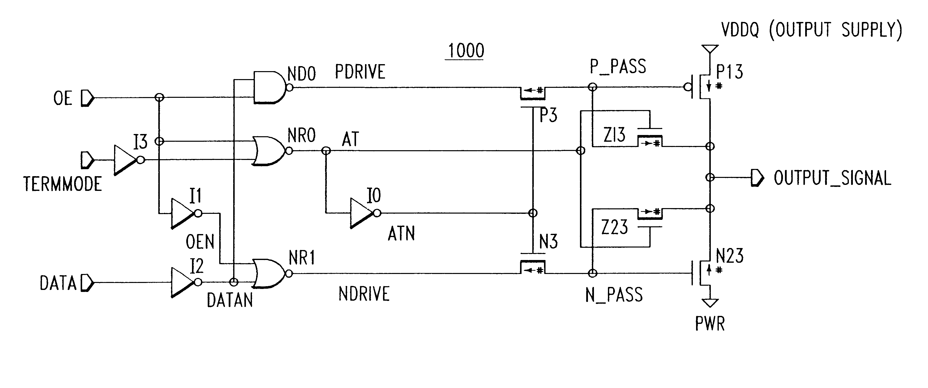
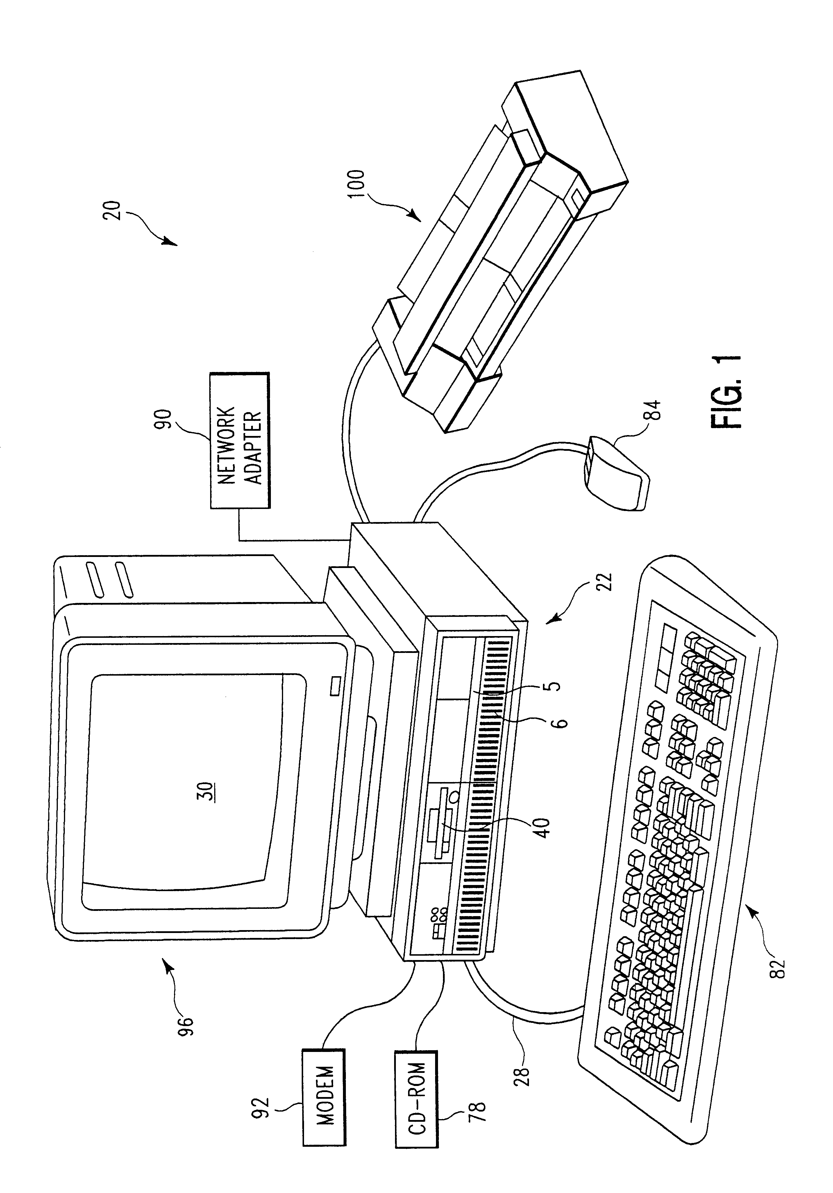
FIG. 1 is a diagram of a data processing system 20 in which the present invention can be practiced. The data processing system 20 includes processor 22, keyboard 82, and display 96. Keyboard 82 is coupled to processor 22 by a cable 28. Display 96 includes display screen 30, which may be implemented using a cathode ray tube (CRT) a liquid crystal display (LCD) an electrode l...


PUM


Abstract

A method and apparatus for providing programmable active termination of transmission lines with substantially reduced DC power consumption.

Description

1. Technical Field of the Present InventionThe present invention generally relates to programmable active terminations, and more specifically to programmable active terminations of Input / Output devices.2. Background of the Present InventionThe electronic industry is in a state of evolution spurred by the recent changes in technology which have allowed greater functionality in smaller devices. This has resulted in the explosion of new found uses for such small devices (e.g. medical, monitoring etc.), as well as greater functionality in increasingly smaller electronic devices.The evolution has caused electronic devices to become an inseparable part of our society. Consumers are now buying and demanding electronic devices which are smaller, more powerful, and faster at unprecedented rates. These demands are constantly driving the electronic industry to exceed limitations which were previously considered unsurpassable.One such area ripe for improvement is how various electronic devices ...

Claims


Application Information

Patent Timeline
Patent Type & Authority Patents(United States)
IPC IPC(8): H03K19/003H04L25/02
CPCH04L25/0298
Inventor BRACERAS, GEORGE M.CONNOR, JOHNHANSEN, PATRICK R.
Owner GLOBALFOUNDRIES INC
Learn More