Planar light source device and liquid crystal display apparatus

a light source device and liquid crystal display technology, applied in lighting and heating devices, instruments, machines/engines, etc., can solve the problems of difficult observation of liquid crystal display, significant power consumption of the planar light source device used in the liquid crystal display apparatus, and mainly consumed power supplied by the charged battery

Inactive Publication Date: 2003-01-07
MITSUBISHI RAYON CO LTD
View PDF12 Cites 58 Cited by
  • Summary
  • Abstract
  • Description
  • Claims
  • Application Information

AI Technical Summary

Problems solved by technology

The power supplied by the charged battery is consumed mainly by the liquid crystal display apparatus, and especially the rate of power consumption of the planar light source device used in the liquid crystal display apparatus is significant.
However, it is not preferable to lower the luminance of the planar light source device by suppressing the power consumption of the device, because it becomes hard to observe the liquid crystal display.
In such a planar light source device, there is a problem that distribution of the emitted light becomes extremely narrow to restrict the range of viewing angle, especially in a plane perpendicular to the linear light source, although the luminance becomes higher.
In addition, there is another problem that it is difficult to apply the planar light source device to large size liquid crystal display apparatus, etc., although the device is suitable for small size liquid crystal display apparatus, etc. which does not necessitate wide range of the viewing angle.
However, in such a planar light source device, it is not possible to sufficiently narrow the distribution of the emitted light in a plane parallel to the light incident face of the light guide, and thus the planar light source device having higher luminance cannot be obtained.
In addition, there is a problem in the device that the luminance within the range of the viewing angle becomes lower, because the amount of light (side lobe) emitted at an angular area of greater than about .times.40.degree. relative to the normal direction of the light emitting surface of the planar light source device, that is, at an angular area without effective range of the viewing angle is relatively large.
However, there is a problem that the luminance is low whereas the range of the viewing angle can be increased, because the vertical angle of the elongated prisms formed on the light guide is 90.degree..
However, even in such cases, the emitted light distribution cannot be broadened sufficiently, and the luminance is lowered.
The reason is as follows: If the ratio r / p is less than 0.1, the distribution of the emitted light from the light guide tends not to be improved sufficiently and the formation of the minute elongated prisms on the surface of the light guide tends to become difficult.
On the other hand, if the ratio r / p is more than 0.7, the distribution of the emitted light from the light guide in a plane parallel to the light incident face of the light guide tends not to become sufficiently narrow and thus the effect to sufficiently enhance the luminance in the normal direction tends not to be obtained.

Method used


Image

  • Planar light source device and liquid crystal display apparatus
  • Planar light source device and liquid crystal display apparatus
  • Planar light source device and liquid crystal display apparatus

Examples


example 2

A first mold having a mirror surface as the transforming surface was provided. A second mold having a roughened surface as the transforming surface was provided by subjecting a metal plate to a blast treatment using glass beads of 125 to 149 micrometers in particle size (FGB-120 produced by Fuji Manufacturing Works Co., Ltd.) under the condition that the distance between the metal plate and a blast nozzle was set to 10 cm and the blast pressure was set to 4 Kg / cm.sup.2. An injection molding process was carried out with use of a pair of molds comprising the first and second molds and of acrylic resin (ACRYPET VH5#000 produced by Mitsubishi Rayon Co., Ltd.) used as injectin molding material, to thereby obtain a light guide in which a first principal surface was mirror surface and a second principal surface was roughened surface having the average slant angle (.theta.a) of 3.1.degree.. The light guide was made to have a wedge plate shape of the dimension of 195 mm.times.253 mm and of 3...


PUM


Abstract

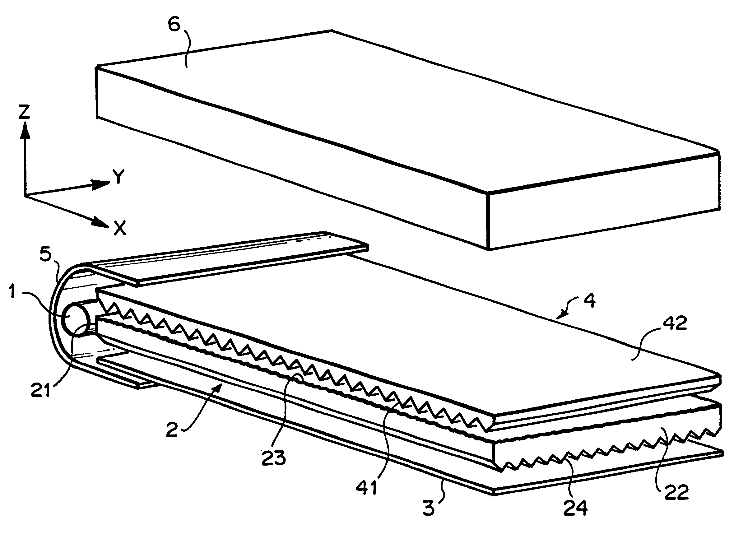
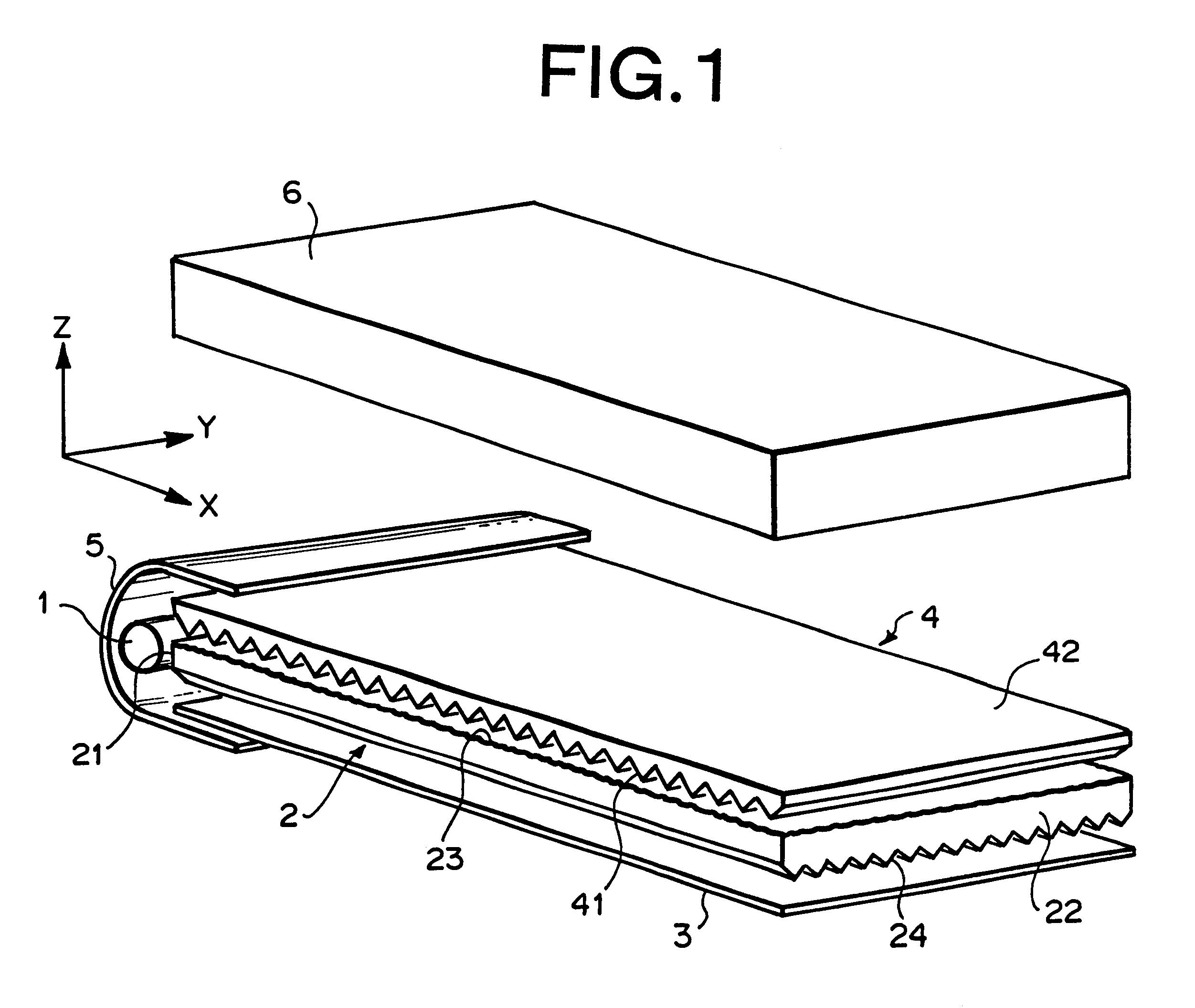
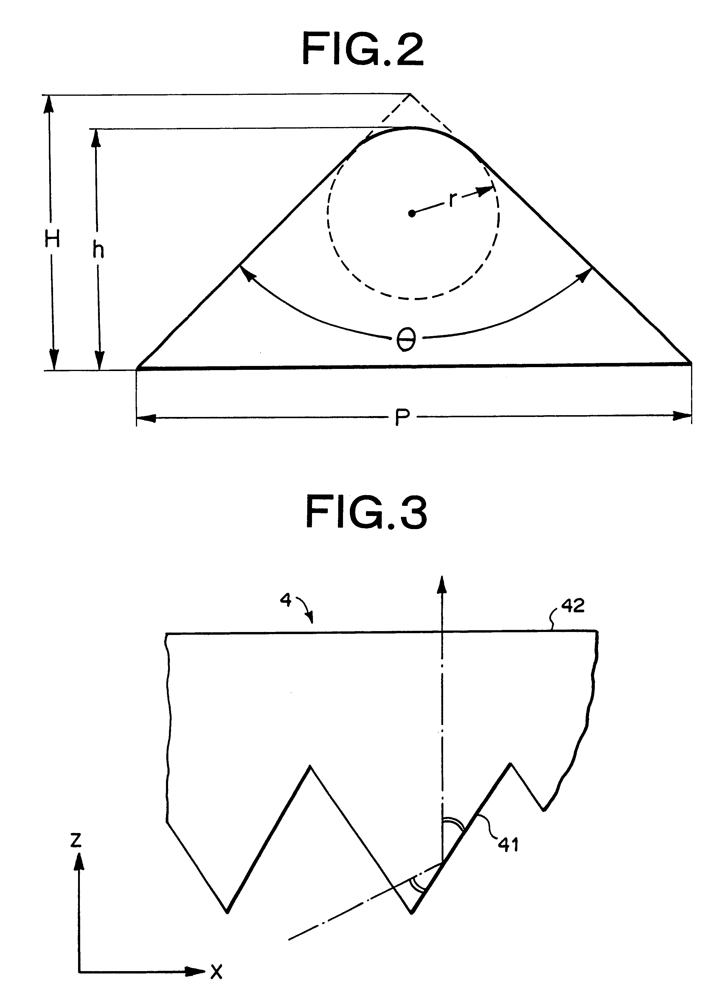
A planar light source device contains a light source (1); a light guide (2) which has a light incident face (21) on at least one side end surface thereof which confronts the light source (1), and a light emitting face (23) on one of two principal surfaces (23, 24) thereof; and a light direction varying sheet (4) which is disposed on the light emitting face (23) of the light guide (2), wherein a back surface (24) of the light guide (2) opposing to the light emitting face (21) is formed as a prism surface which comprises a plurality of elongated prisms each having substantially triangular cross section of a vertical angle within a range of 60 to 80° or 125 to 150° so as to extend in parallel to each other and in perpendicular to the light incident face (21), and a major part of the light emitting face (23) is formed as an uneven surface having an average slant angle of 0.3 to 30°.

Description

The present invention relates to a liquid crystal display apparatus or use in portable personal computers, liquid crystal televisions, personal digital assistants, cellular phones, etc. and an edge-lighting planar light source device used therein.DESCRIPTION OF THE RELATED ARTRecently, a color liquid crystal display apparatus has been widely used in various applications such as in portable personal computers, portable liquid crystal televisions or video built-in type liquid crystal televisions having a color liquid crystal display panel, personal digital assistants, cellular phones, etc. In addition, the amount of information to be processed increases, a demand on the liquid crystal display apparatus is diversified and it becomes necessary to cope with multimedia. Accordingly, there has been energetically promoted to provide the liquid crystal display apparatus having large-sized and super fine displaying panel.The liquid crystal display apparatus comprises mainly a back light and a...

Claims


Application Information

Patent Timeline
Patent Type & Authority Patents(United States)
IPC IPC(8): F21V8/00G02B6/00
CPCG02B6/0053G02B6/0038G02B6/0021G02B6/0046
Inventor MATSUMOTO, HIROKIODA, MASAHARUHAYASHI, YASUKO
Owner MITSUBISHI RAYON CO LTD
Why Eureka
Try Eureka