Synthesis methods for enhancing electromagnetic compatibility and AC performance of power conversion circuits

a power conversion circuit and electromagnetic compatibility technology, applied in the field of high frequency, switched mode power electronic converter circuits, can solve the problems of no universally applicable defined method, no universally applicable synthesis method has been described,

Inactive Publication Date: 2003-01-14
TECHN WITTS
View PDF4 Cites 189 Cited by
  • Summary
  • Abstract
  • Description
  • Claims
  • Application Information

AI Technical Summary

Problems solved by technology

There are some circuits with enhanced electromagnetic compatibility (EMC) that have been known for some time, but to date there has been no revelation of universally applicable defined methods that describe how to synthesize EMC enhanced circuits from equivalent circuits with no EMC enhancements.
No universally applicable synthesis method has been described that allows a designer to transform the flyback converter into the Cuk converter.

Method used


Image

  • Synthesis methods for enhancing electromagnetic compatibility and AC performance of power conversion circuits
  • Synthesis methods for enhancing electromagnetic compatibility and AC performance of power conversion circuits
  • Synthesis methods for enhancing electromagnetic compatibility and AC performance of power conversion circuits

Examples


Embodiment Construction

First Synthesis Method Description

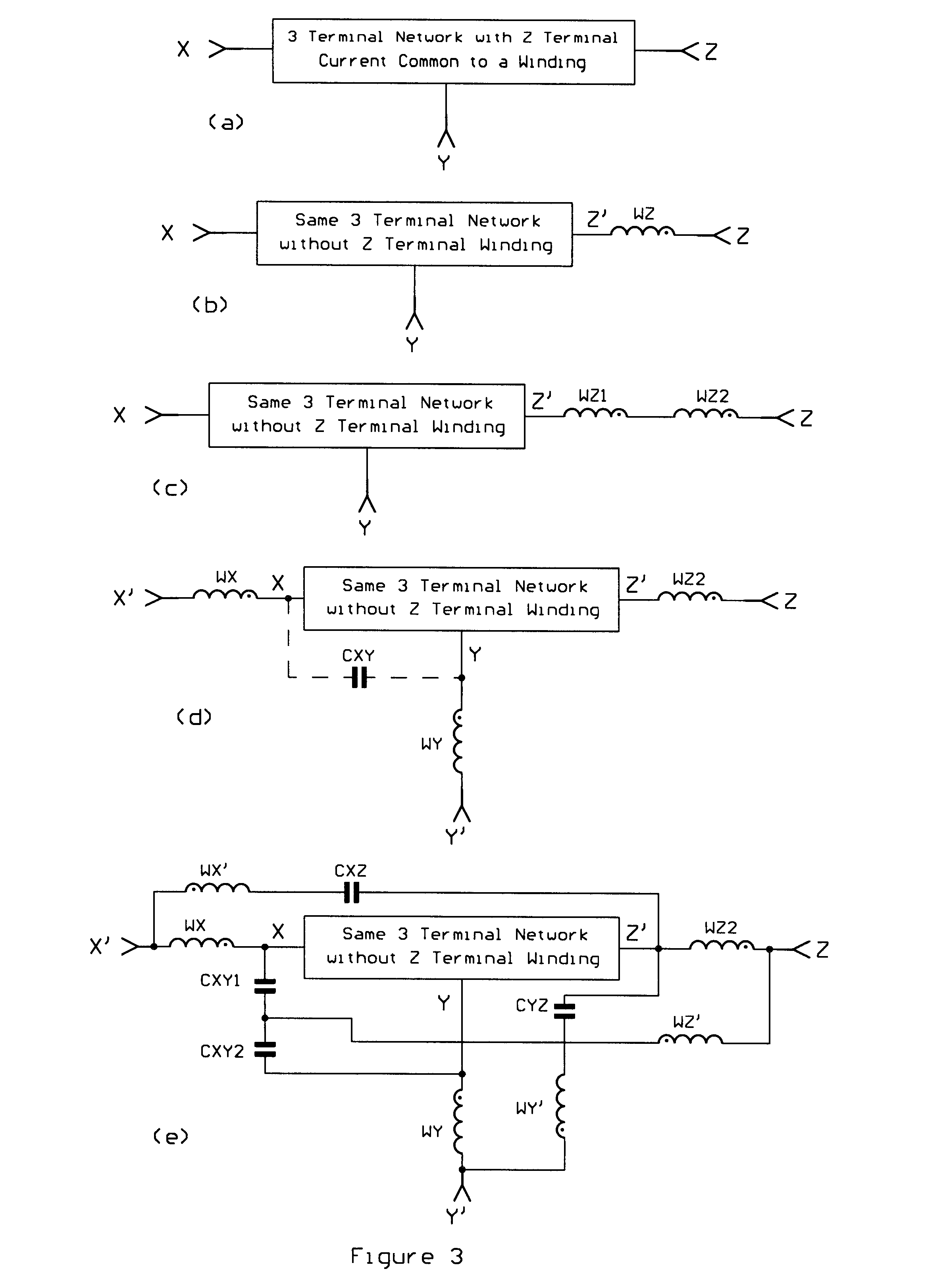
The subject invention describes a first circuit synthesis method applicable to a three terminal power conversion network, in which a winding network of magnetic circuit elements is in series with one of the terminals, is converted into an equivalent three terminal network with superior terminal current properties. For purposes of ease of understanding and clarity the first synthesis method will be described and illustrated for the case in which the winding network contains a single winding. It should be understood that a network of parallel and / or series windings can be substituted for the single winding of the illustrations, as will be illustrated in the examples that follow. The first synthesis method is described in the following steps.

A first synthesis method is described by reference to the figures. Consider an original three terminal network, as illustrated in FIG. 3(a), having an X terminal, a Y terminal, and a Z terminal, in which one of the...


PUM


Abstract

Five circuit synthesis methods, for forming new power conversion circuits with enhanced electromagnetic compatibility and improved AC performance from old circuits with AC performance and / or electromagnetic compatibility deficiencies, are revealed. The new synthesis methods achieve performance improvements without requiring the addition of magnetic cores. In all cases a simple toroidal magnetic core structure is not precluded. In all cases splitting or adding magnetic windings is required, and, in many cases, additional capacitors are required. Many new circuits formed by applying the synthesis methods are revealed. The results achieved by application of the synthesis methods include zero ripple current at all terminals without adding magnetic cores or requiring a complex magnetic circuit element, cancellation of common mode currents, improved control loop bandwidth, and faster transient response.

Description

1. Field of the InventionThe subject invention generally pertains to electronic power conversion circuits, and more specifically to high frequency, switched mode power electronic converter circuits.2. Description of Related ArtPower conversion circuits, in general, create either a pulsed current wave form or a continuous triangular wave form at the terminals of the circuit. To provide an electromagnetically compatible interface, filters are often provided at the terminals. The size and cost of the filters depends on the frequency content and magnitude of the AC ripple components of the terminal currents. A terminal with a pulsed current wave form almost always requires a filter. A triangular terminal current wave form may require a filter although one smaller than would be required by a pulsating current. In addition to the terminal filtering schemes there are ripple current steering schemes that add windings to the chokes and transformers and capacitors to provide a preferred path ...

Claims


Application Information

Patent Timeline
Patent Type & Authority Patents(United States)
IPC IPC(8): H02M3/04H02M3/158H02M3/00
CPCH02M3/158H02M3/005
Inventor WITTENBREDER, JR., ERNEST H.
Owner TECHN WITTS
Why Eureka
Try Eureka