Gear transmission condition monitoring method and apparatus

a condition monitoring and transmission technology, applied in the direction of testing/monitoring control systems, process and machine control, instruments, etc., can solve problems such as motor failure, road failure, and wear of the gear teeth

Inactive Publication Date: 2003-01-14
GE GLOBAL SOURCING LLC
View PDF14 Cites 66 Cited by
  • Summary
  • Abstract
  • Description
  • Claims
  • Application Information

AI Technical Summary

Benefits of technology

It would be advantageous to have a gear condition monitoring method and apparatus which can detect low-level incipient faults in the presence of varying load conditions and interfering signals.

Problems solved by technology

There are several failures that can result in gear problems, including, for example, cracks in gear teeth due to excessive loading and loss of lubrication resulting in gear teeth wear.
Gear problems can lead to gear damage, slipping of pinion gear on the motor shaft, damage to bearings from vibrations and / or loss of lubrication that results in motor failures, and ultimately road failures.

Method used


Image

  • Gear transmission condition monitoring method and apparatus
  • Gear transmission condition monitoring method and apparatus
  • Gear transmission condition monitoring method and apparatus

Examples


Embodiment Construction

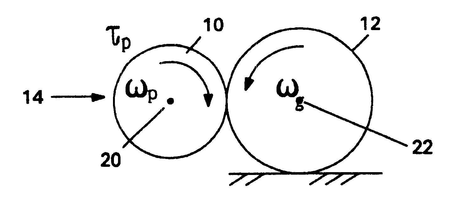
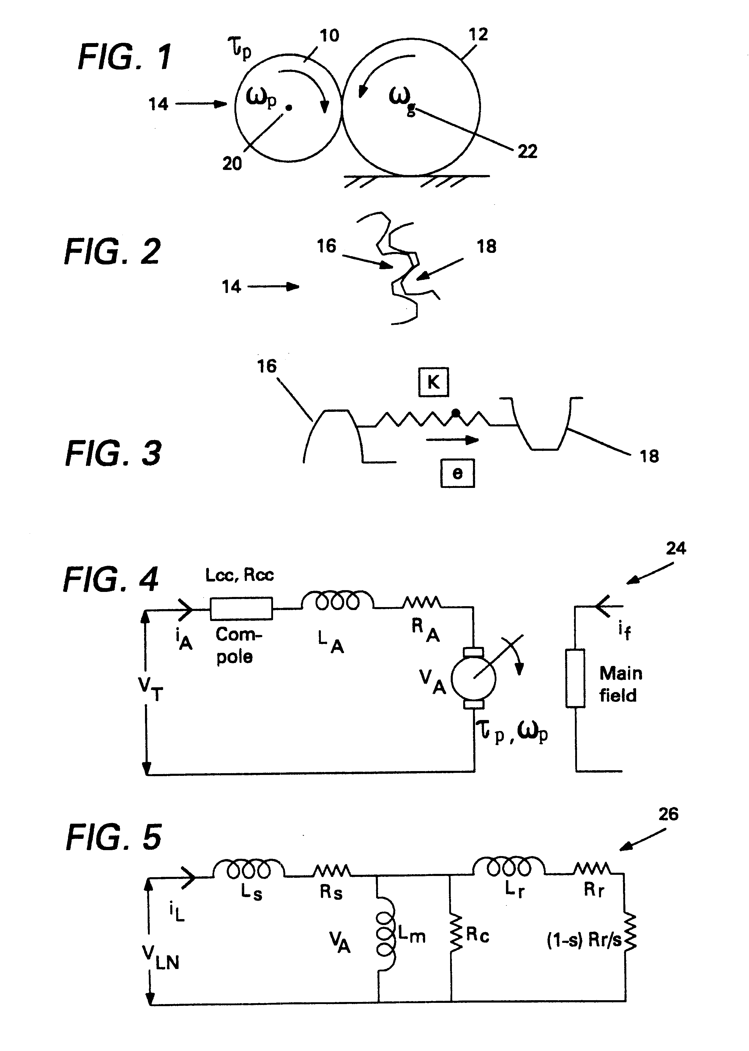
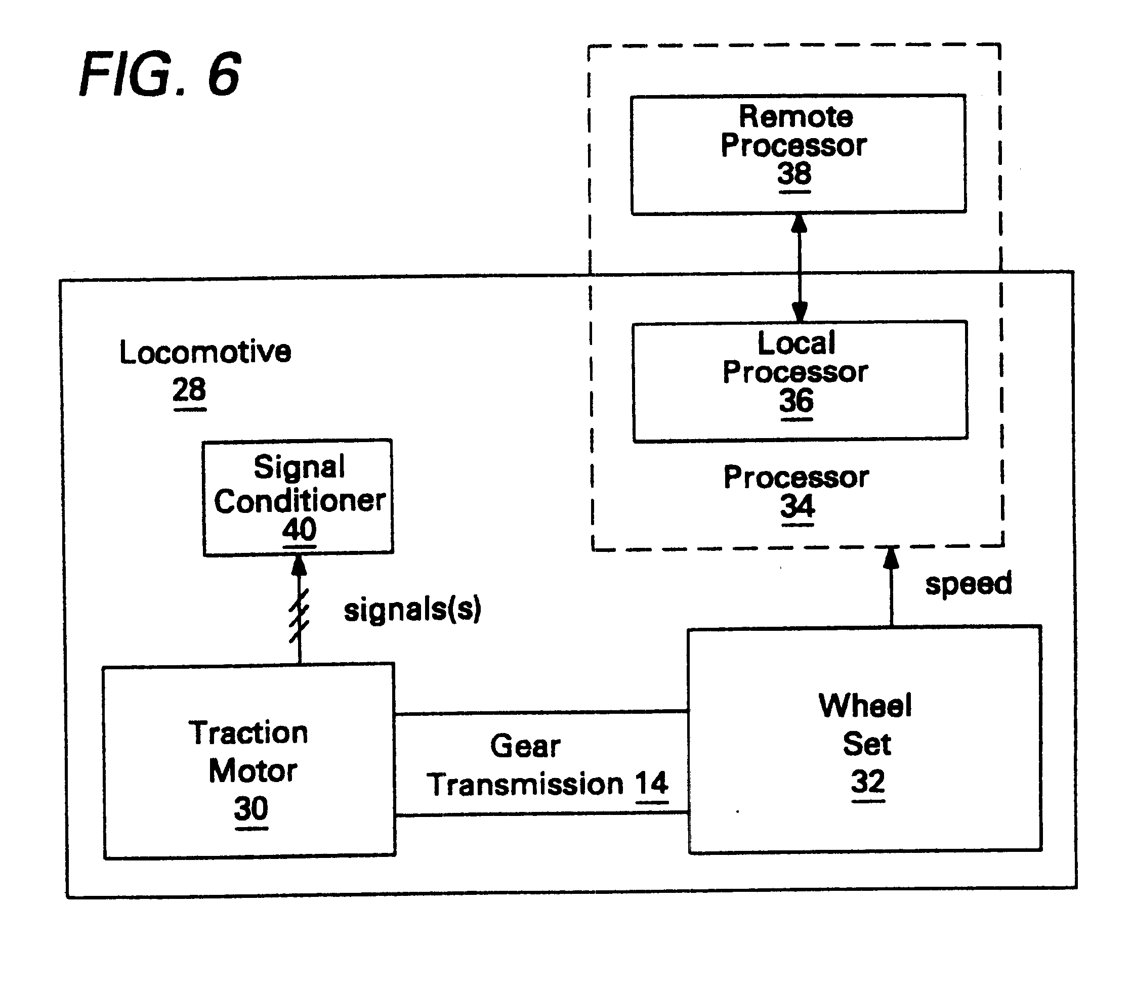
Gear wear and / or cracking increase gear tooth profile errors from the ideal involute profile and result in fluctuations which are periodic with gear mesh frequency. These fluctuations are reflected in axle and motor speeds, which in turn are reflected in motor torque, current and / or voltage depending on the mode of control (speed or torque) and bandwidth of the control system. In case of an alternating current (ac) induction machine, current or voltage signals will have modulations which depend on the mode of operation (for example, six-step or pulse width modulation (PWM)). For six-step mode, the frequency modulations are the line frequency as well as harmonics (5.sup.th, 7.sup.th, 11.sup.th, 13.sup.th, 17.sup.th, 19.sup.th, for example) of the line frequency. For PWM mode, the modulation frequency may be a variable or fixed known frequency, for example. The gear mesh frequency and harmonics will be modulated by these modulation frequencies and show up as sidebands around the modul...


PUM


Abstract

A gear transmission monitoring method includes: forming a good operating condition baseline matrix by, for each of a plurality of different gear mesh frequencies, obtaining a good operating condition signal indicative of gear transmission conditions over a segment of time and transforming the obtained good operating condition signal into a good operating condition time-frequency spectrum; and then obtaining a gear mesh frequency and a test signal over a segment of time, transforming the obtained test signal into a test time-frequency spectrum, and using the gear mesh frequency and the good operating condition baseline matrix to examine the test time-frequency spectrum to monitor gear transmission conditions.

Description

The invention relates generally to machine monitoring and more particularly to gear transmission condition monitoring.Locomotive traction systems include traction motors, gears, gear cases, axles, wheel-sets, and bearings. The gear cases are often lubricated with oil, and the pinion gear is sometimes fitted onto the traction motor shaft using an interference or shrink fit. In some situations, the oil in the gear case also lubricates motor bearings through a passage from the gear case to the bearings. There are several failures that can result in gear problems, including, for example, cracks in gear teeth due to excessive loading and loss of lubrication resulting in gear teeth wear. Gear problems can lead to gear damage, slipping of pinion gear on the motor shaft, damage to bearings from vibrations and / or loss of lubrication that results in motor failures, and ultimately road failures. Prevention of serious gear, bearing, motor and road failures through incipient failure detection wo...

Claims


Application Information

Patent Timeline
Patent Type & Authority Patents(United States)
IPC IPC(8): G01M13/02G05B23/02
CPCG01M13/021G05B23/0256G01M13/028
Inventor REDDY, SURESH BADDAMKLIMAN, GERALD BURTYAZICI, BIRSEN
Owner GE GLOBAL SOURCING LLC
Why Eureka
Try Eureka