Iron-based sintered powder metal body, manufacturing method thereof and manufacturing method of iron-based sintered component with high strength and high density

a technology of iron-based sintered components and metal bodies, which is applied in the direction of metal-working apparatuses, transportation and packaging, etc., can solve the problems of reducing the dimensional accuracy of the component, not being fabricated into the desired shape, and increasing production costs

Inactive Publication Date: 2003-02-04
KAWASAKI STEEL CORP +1
View PDF7 Cites 13 Cited by
  • Summary
  • Abstract
  • Description
  • Claims
  • Application Information

AI Technical Summary

Benefits of technology

Further, in each of the inventions described above, for the composition of the iron-based sintered powder metal body or the composition for the iron-based powder mixture described above, other ingredients than those described above are not particularly restricted so long as most of the remainder (about 85% or more) is iron, and a composition comprising the remainder of Fe and inevitable impurities is preferred.

Problems solved by technology

However, application of the hot pressing technique requires heating facilities for heating the powder to a predetermined temperature which increases production cost and decreases dimensional accuracy of the component due to thermal deformation of the die.
Therefore, when the sintered powder metal body is re-compacted, the re-compacting load increases remarkably and the deformability of the sintered powder metal body is lowered, so that it can not be fabricated into a desired shape.
Accordingly, high strength and high density product can not be obtained.
However, it has been found by the experiment of the present inventors that, under the conditions described above, graphite is completely diffused into the preform to remarkably increase the hardness of the material for sintered preform to make the subsequent cold forging difficult.
However, although the metal powder compacting material (sintered powder metal body) obtained by this method has a high deformability in the re-compaction step, remaining free graphite is eliminated in the subsequent re-sintering to yield elongate voids (pore) to possibly lower the strength of the sintered product.
In view of the quality of the sintered powder metal body, there is no particular restriction for defining the lower limit of the N content but it is industrially difficult to lower the content to about 0.0005 mass % or less.
O is an element contained inevitably and the lower limit is desirably at about 0.02% which is a level not increasing the cost economically and practicable industrially.
On the other hand, when the nitrogen pressure exceeds about 30 kPa, it is difficult to reduce the N content in the sintered powder metal body to about 0.010 mass % or less.

Method used


Image

  • Iron-based sintered powder metal body, manufacturing method thereof and manufacturing method of iron-based sintered component with high strength and high density
  • Iron-based sintered powder metal body, manufacturing method thereof and manufacturing method of iron-based sintered component with high strength and high density

Examples


example 1

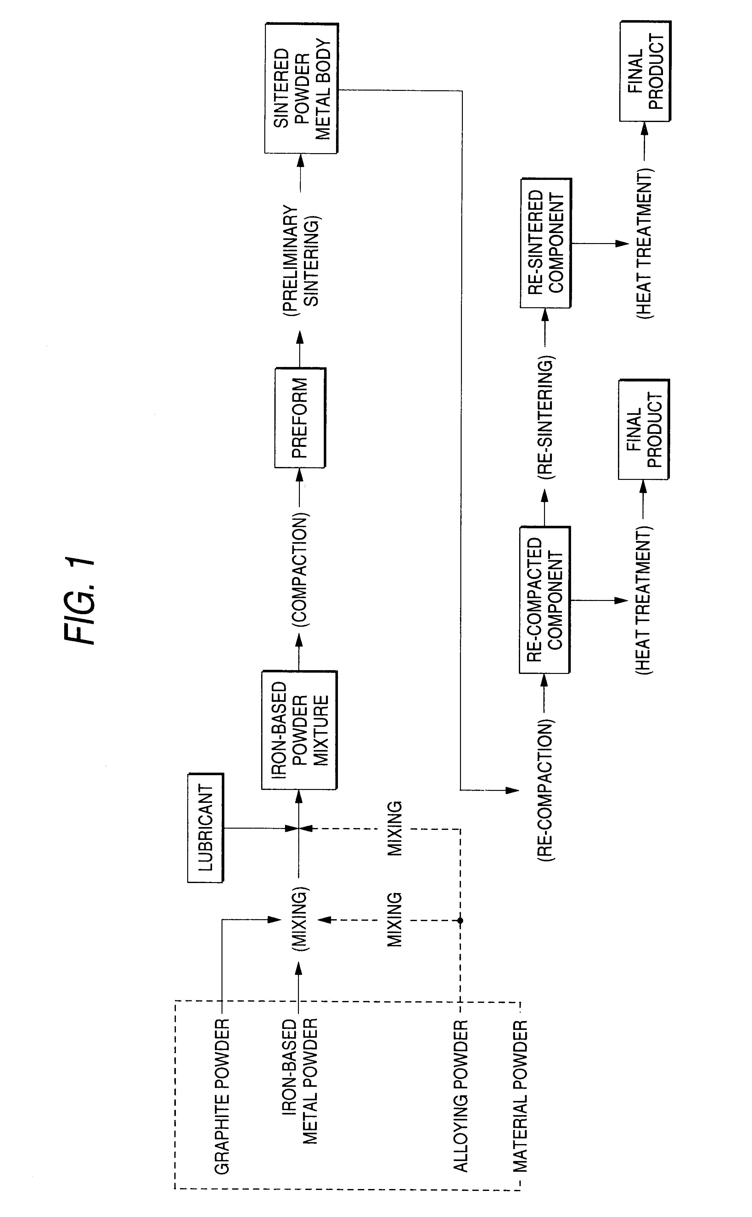
Graphite powders and lubricants of the kinds and the contents shown in Table 1 were mixed to iron-based metal powders shown in Table 1 by a V-mixer to form iron-based powder mixtures.

For the iron-based metal powder, an iron powder A (KIP301A, manufactured by Kawasaki Steel Corporation) and a partially alloyed steel powder B were used. The iron powder A used in this example (Specimen Nos. 1-1 to 1-13, 1-15 to 1-19, 1-22 and 1-23) had an average grain size of about 75 .mu.m, and contained 0.007 mass % C, 0.12 mass % Mn, 0.15 mass % of O and 0.0020 mass % of N and the remainder of Fe and inevitable impurities. As the impurities, 0.02 mass % Si, 0.012 mass % S and 0.014 mass % P were contained. The partially alloyed steel powder B was formed by mixing 0.9 mass % of a molybdenum oxide powder to the iron powder A, keeping the same at 875.degree. C..times.3600 s in a hydrogen atmosphere, and diffusion bonding molybdenum partially on the surface. The partially alloyed steel powder B had a c...

example 2

Graphite powders and lubricants of the kinds and the contents shown in Table 3 were mixed to iron-based metal powders shown in Table 3 by a corn-type mixer to form iron-based powder mixtures.

For the iron-based metal powder, a partially alloyed steel powder C formed by partially alloying Ni and Mo on the surface of iron powder A particles through the same process as in Example 1 was used. The composition of the partially alloyed steel powder C contained 0.003 mass % C, 0.08 mass % Mn, 0.09 mass % O, 0.0020 mass % N, 2.03 mass % Ni and 1.05 mass % Mo. Further, natural graphite was used for the graphite powder and one of zinc stearate, lithium stearate and ethylene bisstearoamide was used as the lubricant. In Table 3, the content of the lubricant in the iron-based powder mixture is indicated by parts by weight based on 100 parts by weight for the total amount of the iron-based metal powder and the graphite powder.

The iron-based mixed powder was charged in a die, compacted at the room t...

example 3

Graphite powders and lubricants of the kinds and the contents shown in Table 5 were mixed to iron-based metal powders shown in Table 5 by a corn-type mixer to form iron-based powder mixtures.

For the iron-based metal powder, a pre-alloyed steel powder D formed by a water atomizing method (KIP5MOS, manufactured by Kawasaki Steel Corporation) was used. The composition of the pre-alloyed steel powder D comprised 0.004 mass % C, 0.20 mass % Mn, 0.11 mass % 0, 0.0021 mass % N and 0.60 mass % Mo and the remainder of Fe and inevitable impurities. As the imparities, 0.02 mass % Si, 0.006 mass % S and 0.015 mass % P were contained. The average particle size of the powder D was about 89 .mu.m. Further, natural graphite was used for the graphite powder and zinc stearate was used for the lubricant.

In Table 5, the content of the lubricant in the iron-based powder mixture is indicated by parts by weight based on 100 parts by weight in total for the iron-based metal powder and the graphite powder.

T...


PUM

PropertyMeasurementUnit
pressureaaaaaaaaaa
temperatureaaaaaaaaaa

Abstract

An sintered iron-based powder metal body with outstandingly lower re-compacting load and having a high density and a method of manufacturing an iron-based sintered component with fewer pores of a sharp shape and having high strength and high density, the method comprising mixing,an iron-based metal powder containingat most about 0.05% of carbon,at most about 0.3% of oxygen,at most about 0.010% of nitrogen,with at least about 0.03% and at most about 0.5% of graphite powder and a lubricant, preliminarily compacting the mixture into a preform, the density of which is about 7.3 Mg / m3 or more, and preliminarily sintering the preform in a non-oxidizing atmosphere in which a partial pressure of nitrogen is about 30 kPa or less at a temperature of about 1000° C. or higher and about 1300° C. or lower, thereby forming a sintered iron-based powder metal body with outstandingly lower re-compacting load and having high deformability, the density of which is about 7.3 Mg / m3 or more and which contains at least about 0.10% and at most about 0.50 of carbon, at most about 0.010% of oxygen and at most about 0.010% of nitrogen, and which comprises at most about 0.02% of free carbon, and, further applying re-compaction and re-sintering and / or heat treatment thereby forming a sintered component, as well as the method alternatively comprising applying preliminary sintering in an atmosphere with no restriction of the nitrogen partial pressure and then annealing instead of the sintering step, thereby obtaining a sintered iron-based powder metal body with the nitrogen content of at most about 0.010%.

Description

1. Field of the InventionThis invention relates to an iron-based sintered component formed of an iron-based metal powder as a raw material and suitable to machinery parts, or an iron-based powder metal body as an intermediate material suitable to manufacture of the sintered iron-based component.2. Description of the Related ArtPowder metallurgical technology can produce a component having a complicated shape as a "near net shape" with high dimensional accuracy and can markedly reduce the cost of cutting and / or finishing. In such a near net shape, almost no mechanical processing is required to obtain or form a target shape. Powder metallurgical products are, therefore, used in a variety of applications in automobiles and other various fields. For reduction in size and weight of the components, demands have recently been made on such powder metallurgical products to have higher strength. Specifically, strong demands have been made on iron-based powder products (sintered iron-based com...

Claims


Application Information

Patent Timeline
Patent Type & Authority Patents(United States)
IPC IPC(8): B22F3/10C22C33/02B22F3/12
CPCB22F3/1007C22C33/02C22C33/0264B22F3/02B22F3/10C22C33/0207B22F1/0096B22F2998/10B22F2999/00B22F1/148B22F3/12
Inventor NAKAMURA, NAOMICHIUENOSONO, SATOSHIUNAMI, SHIGERUFUJINAGA, MASASHIYOSHIMURA, TAKASHIIIJIMA, MITSUMASAKOIZUMI, SHINANMA, HIROYUKIHATAI, YASUO
Owner KAWASAKI STEEL CORP
Why Eureka
Try Eureka