Method and apparatus for calculating RMS value

a technology of rms value and method, applied in the field of computing rms value, can solve the problems of insufficient method of rms calculation for wide frequency range applications or high frequency applications, particularly computational means for calculating rms, and inability of microprocessors to perform other system functions during rms calculation

Inactive Publication Date: 2003-02-04
ROCKWELL TECH
View PDF16 Cites 38 Cited by
  • Summary
  • Abstract
  • Description
  • Claims
  • Application Information

AI Technical Summary

Problems solved by technology

In a microprocessor controlled system the means for calculating RMS may be particularly computationally inefficient.
That is to say that often RMS calculations must be made in the foreground, thereby making the microprocessor unavailable to perform other system functions during the RMS calculations.
Disadvantageousl

Method used


Image

  • Method and apparatus for calculating RMS value
  • Method and apparatus for calculating RMS value
  • Method and apparatus for calculating RMS value

Examples


Embodiment Construction

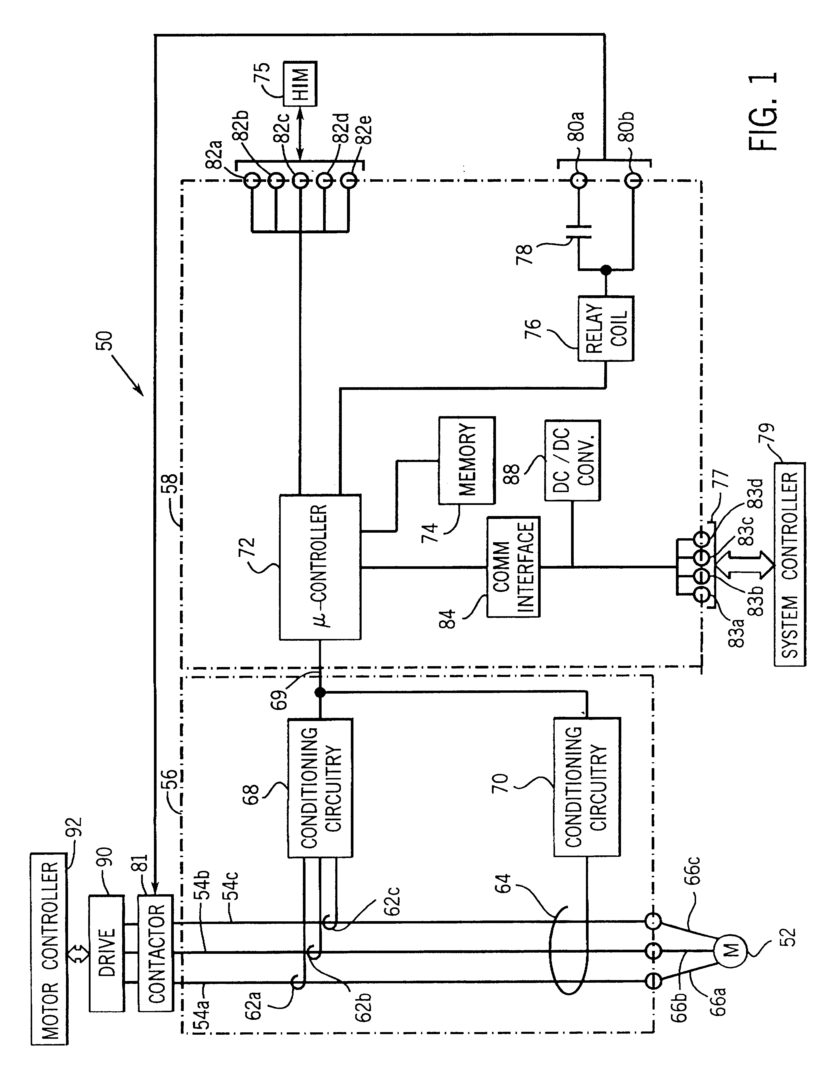
Turning now to the drawings, and referring first to FIG. 1, an exemplary overload relay 50 for monitoring and interrupting current flow provided to a motor 52 via power conductors 54a, 54b, and 54c, and 66a, 66b and 66c is illustrated. Relay 50 includes a sensing module 56 and a control module 58. Sensing module 56 includes sensors 62a, 62b, 62c, and 64, which are arranged to monitor the current flow through power conductors 54a, 54b, and 54c. Sensors 62a-c and 64 may be Hall effect sensors or current transformers having a core through which power conductors 54a-c pass. Sensors 62a, 62b, and 62c are configured to monitor the current flow in power conductors 54a, 54b, and 54c, respectively, and provide output signals representative of the individual phase currents, L1, L2 and L3. Sensor 64 is configured simultaneously to monitor the current flow in all three power conductors and provide an output signal representative of a vector sum of the phase currents. This vector sum is also ref...


PUM


Abstract

A technique for computing RMS values for sampled waveforms. More specifically, a technique for computing RMS values for periodic waveforms, using data taken from a full waveform, a half waveform or some other portion of a waveform is described. Each RMS calculation is based on a different algorithm and provides accurate, real time data.

Description

1. Field of the InventionThe present invention relates generally to calculating RMS values. More particularly, the present invention relates to a technique for computing RMS values for sampled waveforms, in which a number of samples is difficult to predict. The technique permits the computation of accurate values in real time, in a processing routine designed to perform other real time operations as well.2. Description of the Related ArtA variety of systems, particularly in the industrial control field, require sampling of data and analysis of the data to make decisions based on the measurements. The data and analysis of the data can represent various parameters, such as current, voltage, power and so forth. In a number of applications it is particularly useful to analyze sampled data based on a set of samples to determine a root-mean-squared (RMS) value. The RMS value calculations are useful in condensing a series comprising a plurality of measurements into one useful measurement.O...

Claims


Application Information

Patent Timeline
IPC IPC(8): G05B21/00G05B21/02
CPCG05B21/02
Inventor JANSEN, RONALD N.HAENSGEN, STEVEN T.
Owner ROCKWELL TECH
Why Eureka
Try Eureka