

Shock absorbing device for shoe sole
a technology of shock absorption device and shoe sole, which is applied in the field of shoe sole, can solve the problems of affecting the lightweight properties and stability of the shoe sole, bringing about compressive transformation of the corrugated portions, and not ensuring sufficient shock absorption ability
- Summary
- Abstract
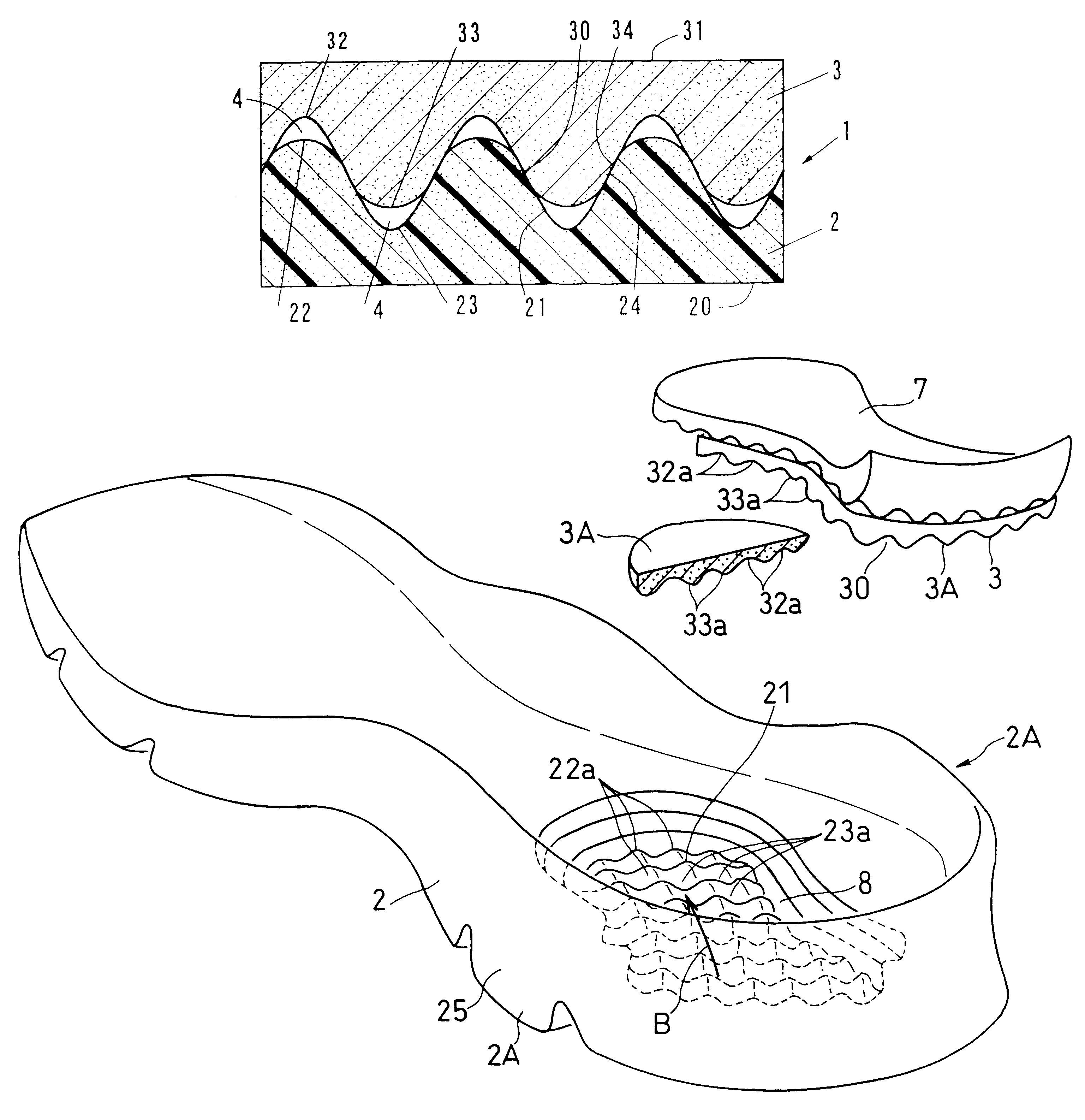
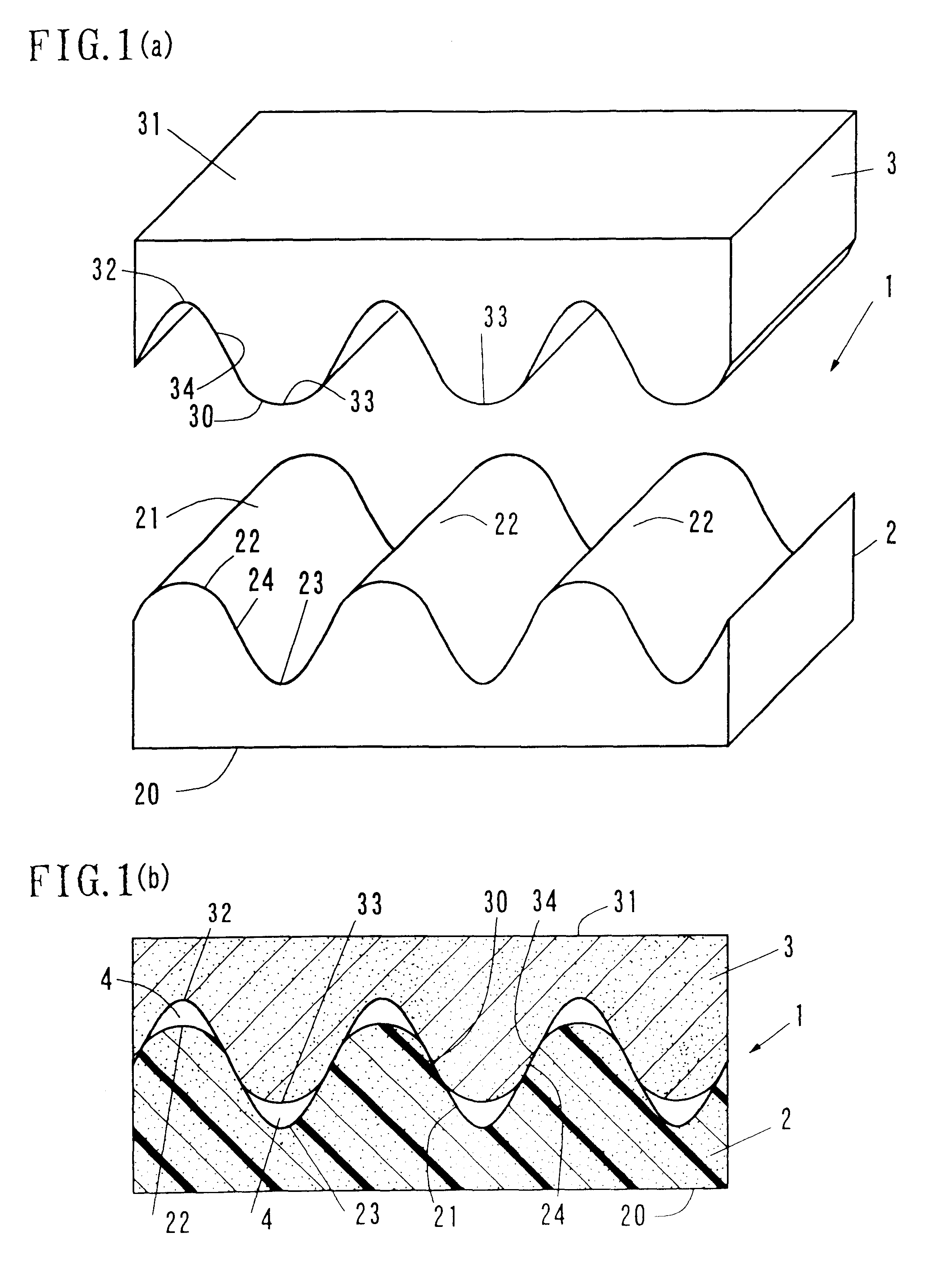
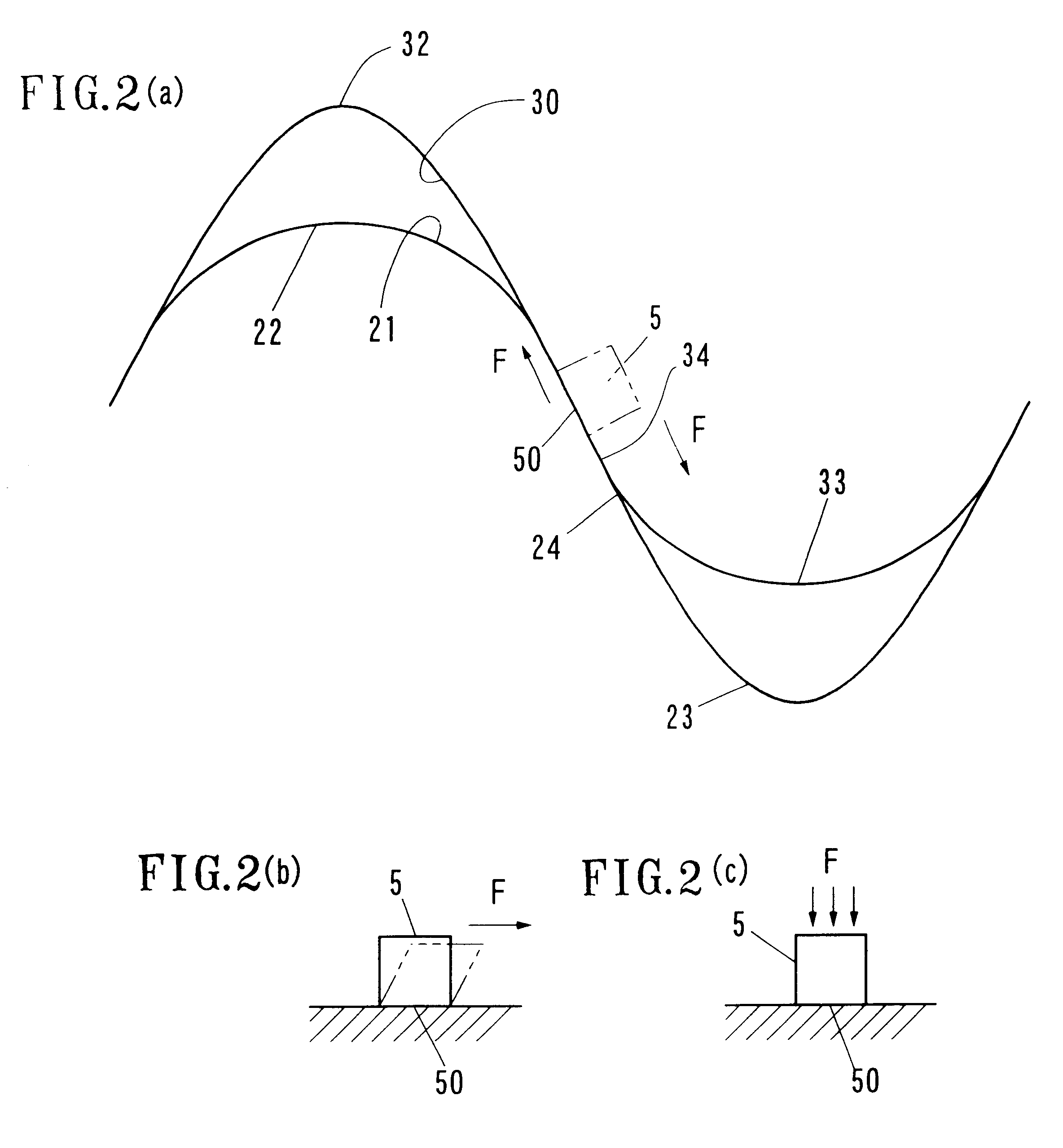
- Description
- Claims
- Application Information
AI Technical Summary
Benefits of technology
Problems solved by technology
Method used
Image

Examples
Embodiment Construction
6 3 0.5 12 0.0057 Test Example 2 6 3.6 0.6 12 0.0067 Test Example 3 6 3.9 0.65 12 0.007 Test Example 4 6 4.2 0.7 12 0.0069 Test Example 5 6 4.5 0.75 12 0.0061 Test Example 6 6 4.8 0.8 12 0.0056 Test Example 7 6 5.4 0.9 12 0.0045 TYPE 2 Test Example 11 7.8 3.9 0.5 12 0.0069 Test Example 12 6.5 3.9 0.6 12 0.0076 Test Example 13 6 3.9 0.65 12 0.0073 Test Example 14 5.57 3.9 0.7 12 0.0071 Test Example 15 5.2 3.9 0.75 12 0.0066 Test Example 16 4.875 3.9 0.8 12 0.0061 Test Example 17 4.588 3.9 0.85 12 0.006 TYPE 3 comparative 6 6 1 12 0.0044 Example 1 TYPE 4 comparative 6 none 0 12 0.0060 Example 2
The cushioning in the table represents the quantized damping of the low-frequency components which the human body feels uncomfortable, which quantization is achieved by performing each frequency-based decomposition of shocks which the weight corresponding to the foot undergoes upon the impact of the weight against the models. It has been verified from the comparison with the sensory tests that l...
PUM
| Property | Measurement | Unit |
|---|---|---|
| hardness | aaaaa | aaaaa |
| lattice points | aaaaa | aaaaa |
| energy | aaaaa | aaaaa |
Abstract
Description
Claims
Application Information