Device for connecting a pipe end to a member

a technology for connecting devices and pipes, which is applied in the direction of sleeve/socket joints, joints with sealing surfaces, and fluid pressure sealed joints, etc. it can solve the problems of pipe back-off, said liquid runs the risk of stagnant therein, and is particularly difficult to clear, and achieves a small number of parts. , the effect of simple structur

Inactive Publication Date: 2003-02-11
LEGRIS
View PDF9 Cites 100 Cited by
  • Summary
  • Abstract
  • Description
  • Claims
  • Application Information

AI Technical Summary

Benefits of technology

The sleeve thus performs the two functions of constituting a resilient abutment and of constituting a seal

Problems solved by technology

Penetration of the claws into the outside surface of the pipe also causes the pipe to back off.
While a liquid is circulating through the coupling zone, some of the liquid runs the risk or penetrating into said gap and into the portion of this clearance defined by the sealing ring, and said liquid runs the risk of remaining constant

Method used


Image

  • Device for connecting a pipe end to a member
  • Device for connecting a pipe end to a member
  • Device for connecting a pipe end to a member

Examples


Embodiment Construction

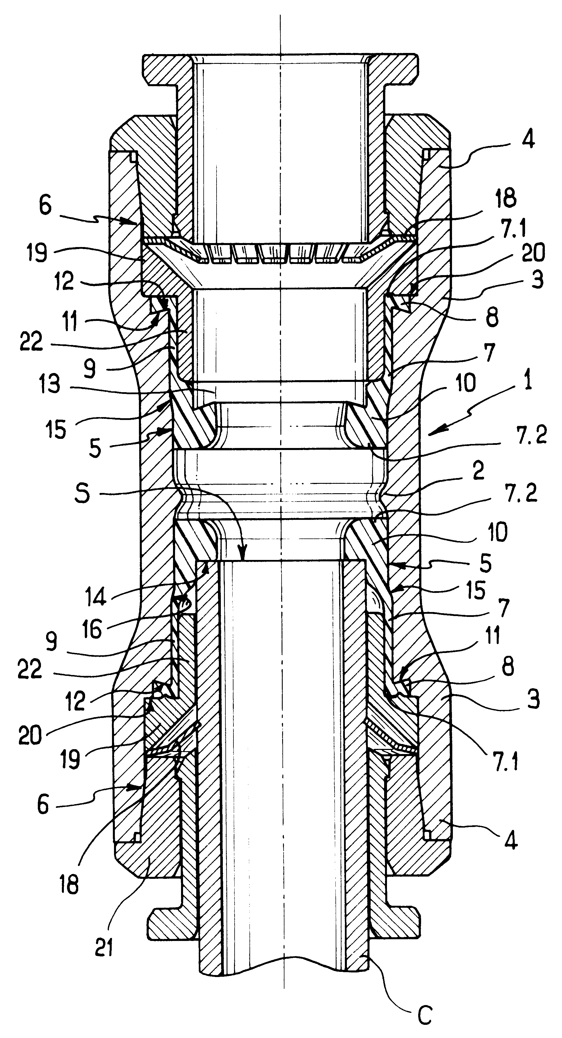
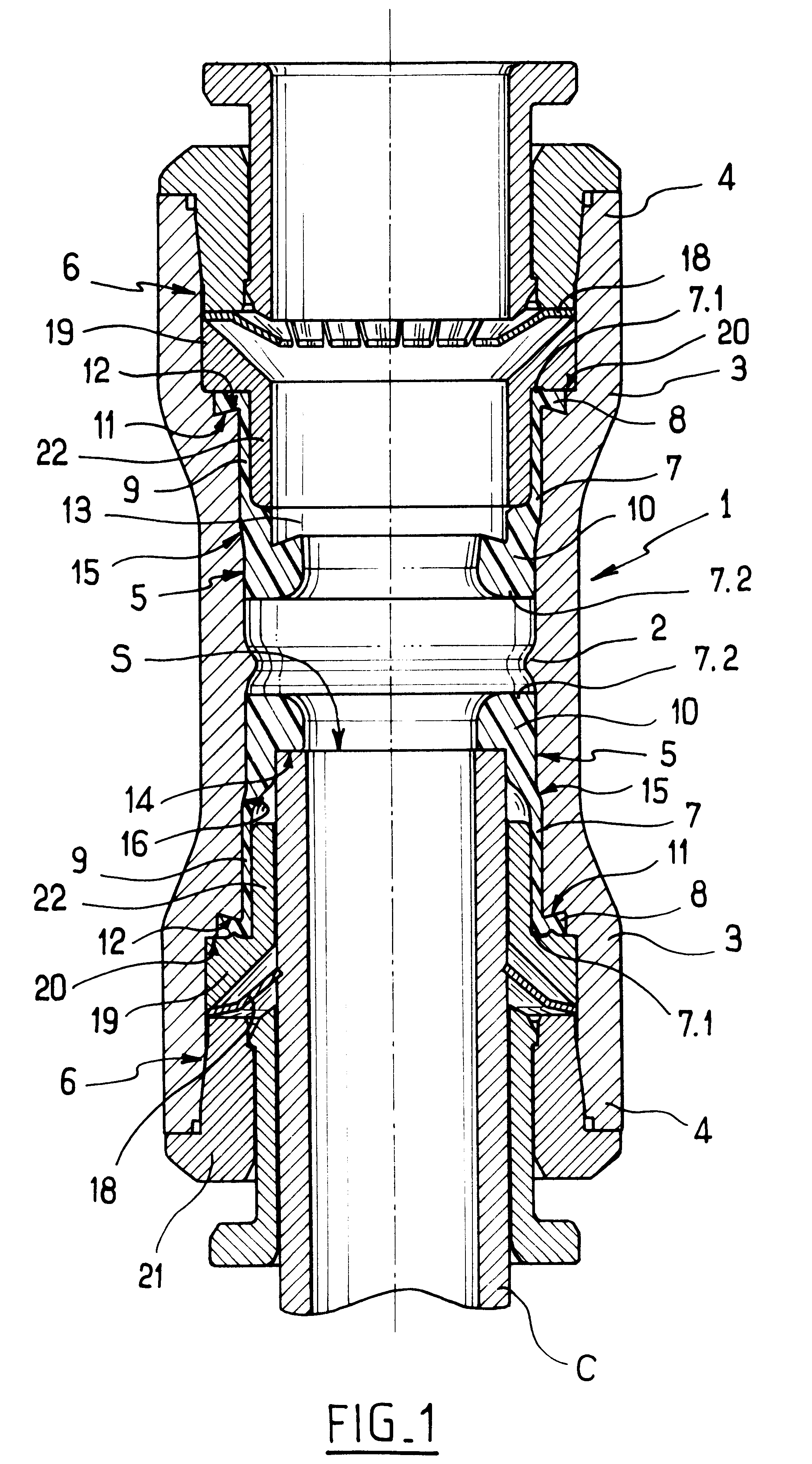
With reference to the figures, the connection device of the invention as described herein is for coupling together two pipe ends C in a liquid transport circuit. The connection device could also be arranged to enable a pipe end to be connected to a member for delivering or receiving fluid, e.g. a pump, a tank, etc.

With reference more particularly to FIGS. 1 and 2, the connection device comprises a tubular endpiece given overall reference 1 and having a central annular swelling 2 projecting into the inside thereof with an inside diameter that is slightly smaller than the inside diameter of the endpiece 1 so as to subdivide the endpiece 1 into two identical sections 3 each for coupling to a respective pipe end C. Each coupling section 3 has a free end 4 remote from the other coupling section 3 through which it receives the pipe end C that is to be inserted into the coupling section 3.

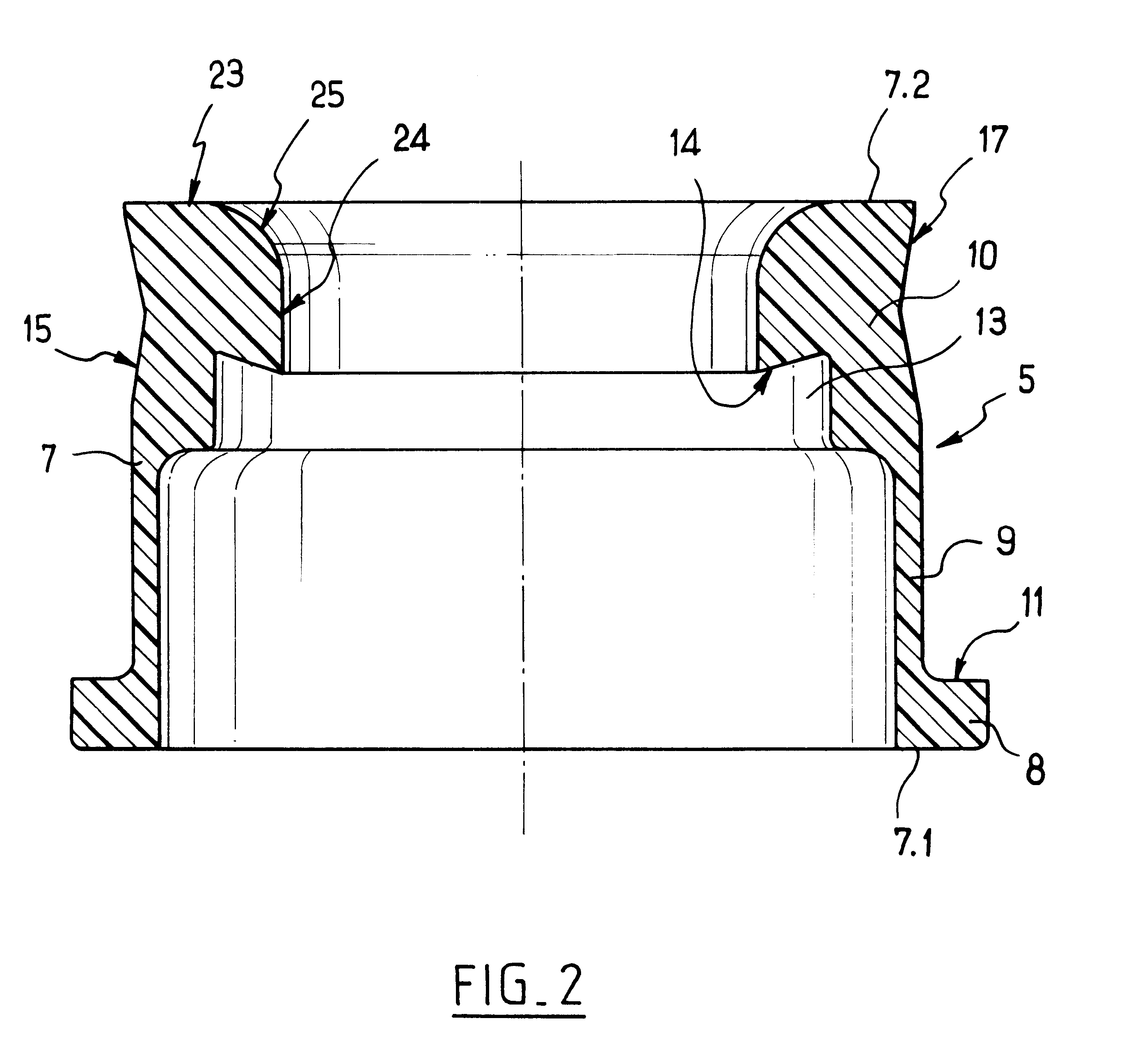
Each coupling section 3 is provided internally with a resilient abutment 5 against further engagement ...


PUM


Abstract

A device for connecting a pipe end to a member. The device has a tubular endpiece with a first end secured to the member and a second end through which the pipe end can be engaged in the endpiece. The endpiece is provided internally with an abutment against engagement of the pipe end and a way for securing the pipe end in leakproof manner inside the endpiece, and a sleeve that is elastically deformable at least in an axial direction. The sleeve is fixable axially in the endpiece and, towards the first end of the endpiece, has an end provided with an annular internal shoulder for coming into abutment against an end face of the pipe end so as to form the abutment against engagement of the pipe end.

Description

The present invention relates to a device for connecting one end of a pipe to a member of a circuit for conveying fluid under pressure, such as another pipe, a tank, a pump, . . .Such a connection device generally comprises a tubular endpiece secured to the member and provided with an internal annular shoulder against which the end of the pipe comes into abutment, and means for securing said end in leakproof manner within the tubular endpiece. These means comprise a claw washer mounted in the tubular endpiece and an O-ring received in the tubular endpiece between the shoulder and the claw washer.While the pipe end is being coupled, the end of the pipe is engaged in the tubular endpiece until it comes into abutment against the annular shoulder. The claws are then pressed against the outside surface of the pipe end, and the O-ring is in close contact with the outside surface of the pipe end, thereby making the coupling leakproof. When the circuit in which the connection device is inst...

Claims


Application Information

Patent Timeline
IPC IPC(8): F16L37/00F16L37/091F16L21/08F16L21/02F16L37/12
CPCF16L37/091F16L37/0915
Inventor LE QUERE, PHILIPPE
Owner LEGRIS
Why Eureka
Try Eureka