In-tank fuel supply apparatus

a fuel supply and tank technology, applied in the direction of machines/engines, separation processes, filtration separation, etc., can solve the problem of high manufacturing cos

Inactive Publication Date: 2003-02-18
MITSUBISHI ELECTRIC CORP
View PDF7 Cites 38 Cited by
  • Summary
  • Abstract
  • Description
  • Claims
  • Application Information

AI Technical Summary

Problems solved by technology

While the pressure regulator 10 of FIG. 14 has good sealing performance, it has the drawback that it is expensive to manufac

Method used


Image

  • In-tank fuel supply apparatus
  • In-tank fuel supply apparatus
  • In-tank fuel supply apparatus

Examples


Embodiment Construction

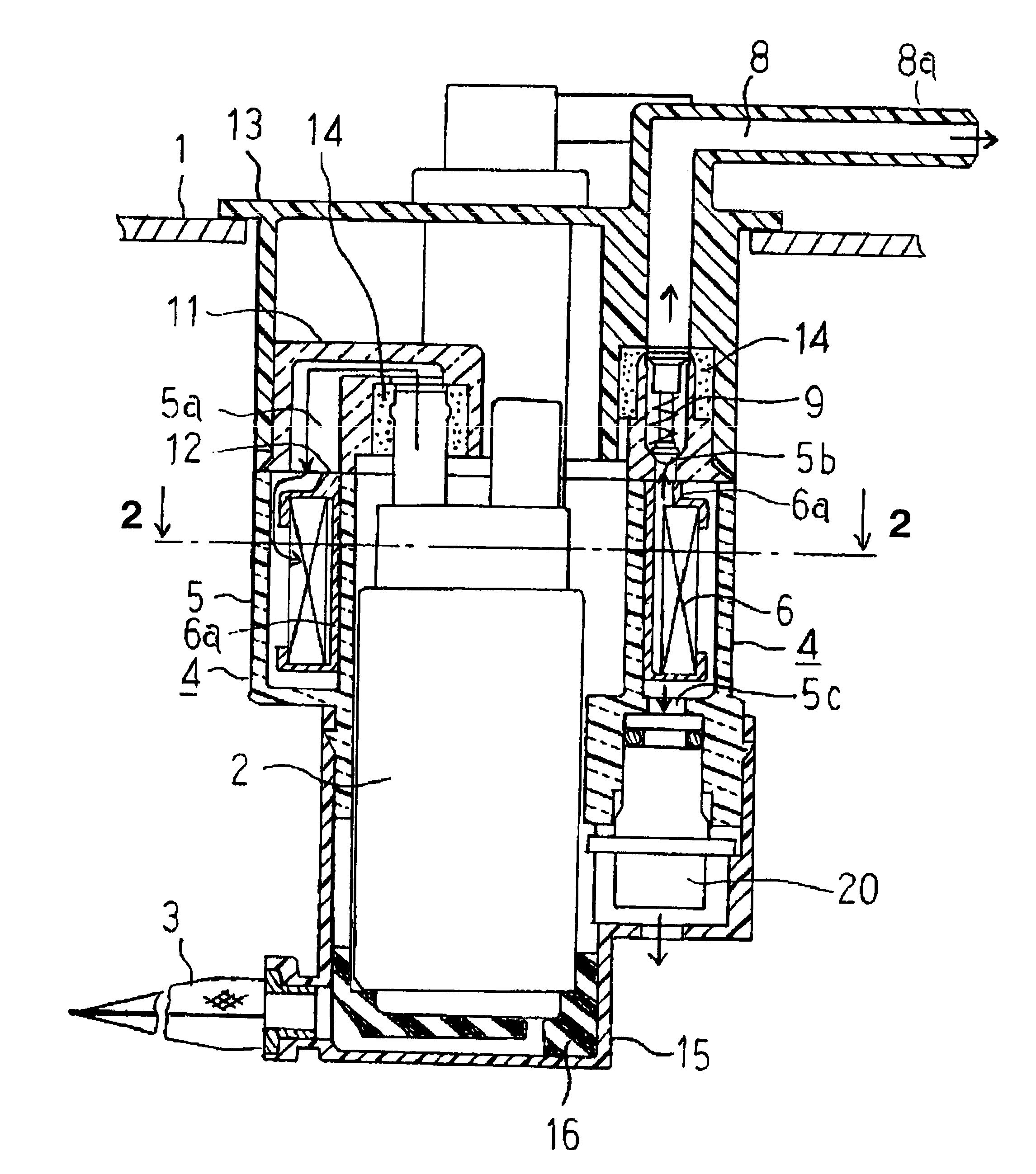
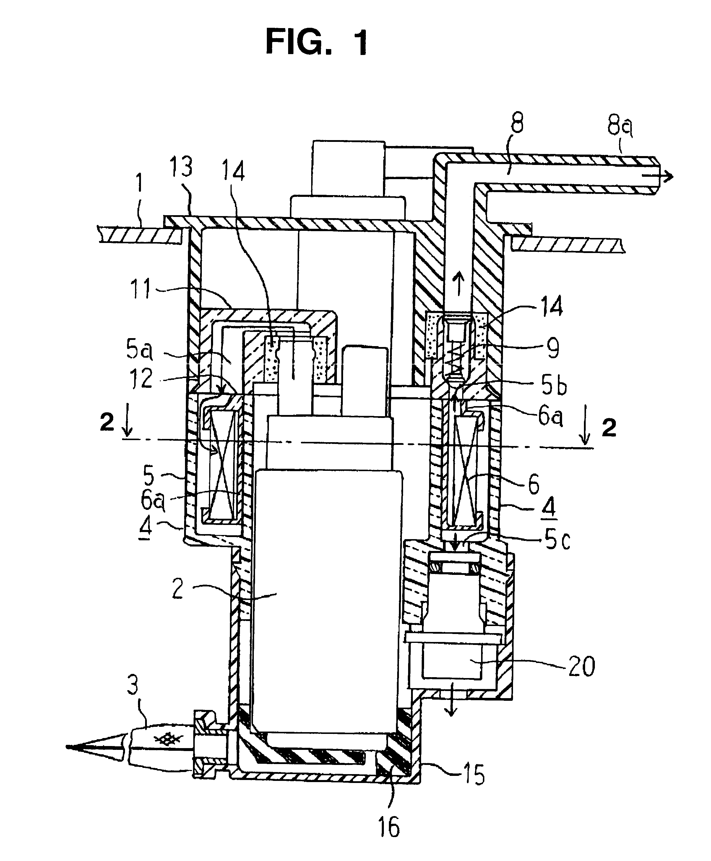
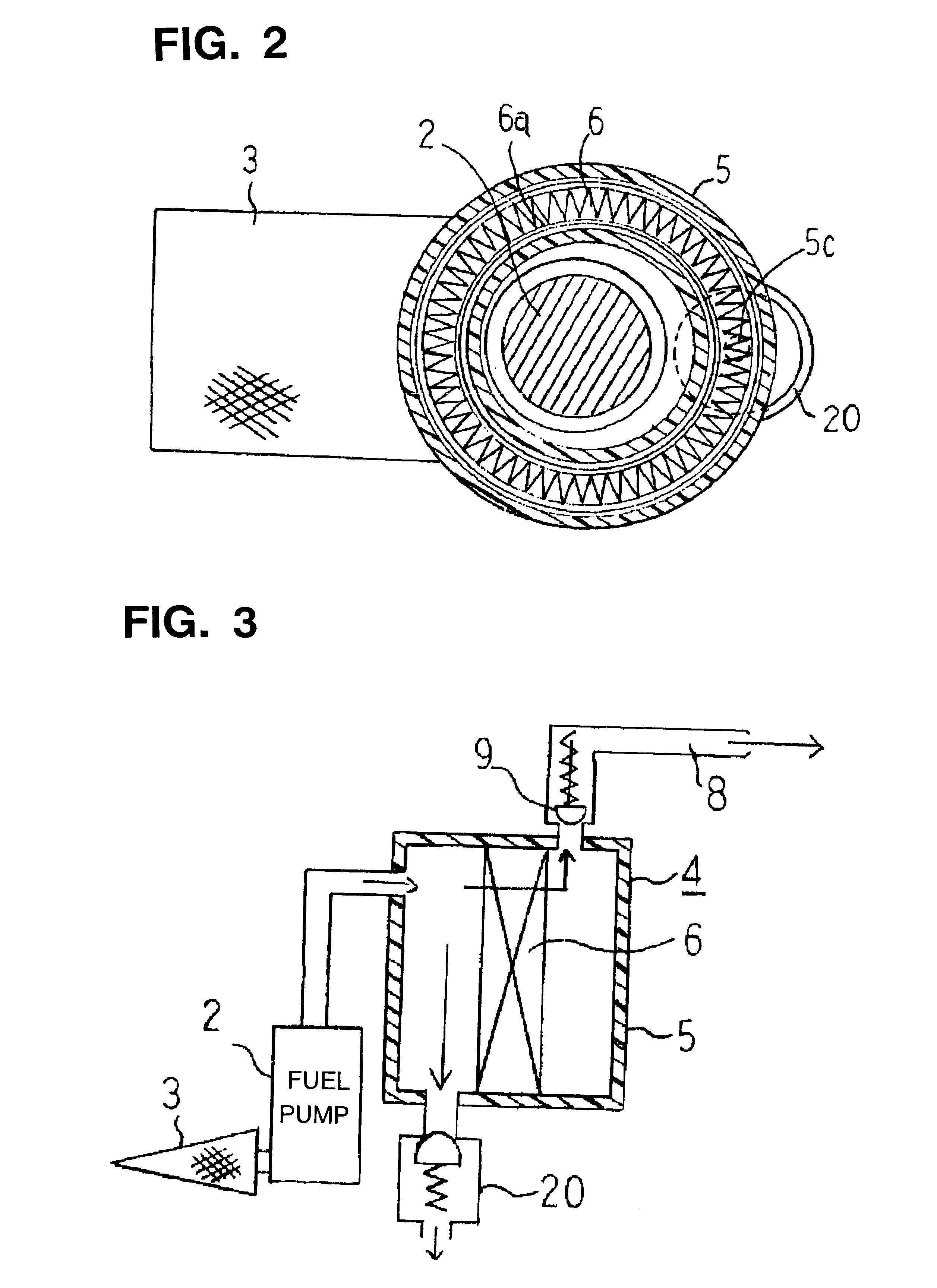
A number of preferred embodiments of a fuel supply apparatus according to the present invention will be described with reference to the accompanying drawings. FIGS. 1-4 illustrate a first embodiment. FIG. 1 is a cross-sectional elevation of this embodiment, FIG. 2 is a cross-sectional view taken along line 2--2 of FIG. 1, FIG. 3 is a schematic illustration of this embodiment, and FIG. 4 is an enlarged cross-sectional elevation of the pressure regulator of this embodiment.

In these figures, elements 1-6, 8, and 9 are the same as explained with respect to FIGS. 12-14, so an explanation of these elements will be omitted.

The illustrated fuel supply apparatus includes a filter element support wall 6a which supports the filter medium of the filter element 6 and separates fuel which has been filtered from unfiltered fuel within the main housing 5. The element support wall 6a is made from an electrically conducting resin, and it acts as a conductor for dissipating static electricity which is...


PUM

PropertyMeasurementUnit
Flow rateaaaaaaaaaa

Abstract

A fuel supply apparatus for installation in a fuel tank includes a fuel pump, a housing, and a filter element disposed in the housing and having an upstream side communicating with the discharge port of the fuel pump. A check valve communicates with a downstream side of the fuel filter, and a pressure regulator communicates with the upstream side of the filter element. A sedimentation flow path may be provided for removing sediment from fuel discharged from the pressure regulator. The sedimentation flow path may be substantially cylindrical vortex spaces between fins disposed on the inner periphery of the pump holder and has blind holes at the bottom for trapping the sediments.

Description

REFERENCE TO RELATED APPLICATIONSThis application is based on Japanese Patent Application No. 2000-270265, filed in Japan on Sep. 6, 2000, the contents of which are hereby incorporated by reference.1. Field of the InventionThis invention relates to an in-tank fuel supply apparatus for installation in a fuel tank of a vehicle, for example. In particular, it relates to an in-tank fuel supply apparatus in which a fuel pump, a fuel filter, a pressure regulator, and a check valve are part of an assembly which can be installed in a fuel tank as a single unit.2. Description of the Related ArtFIG. 12 is a cross-sectional elevation of a conventional in-tank fuel supply apparatus disclosed in Japanese Published Unexamined Patent Application Hei 11-241659 having a fuel pump, a fuel filter, a pressure regulator, and a check valve combined as part of an assembly for installation in a fuel tank. FIG. 13 is a schematic illustration of the apparatus of FIG. 12, and FIG. 14 is an enlarged cross-sect...

Claims


Application Information

Patent Timeline
IPC IPC(8): F02M37/10F02M37/08F02M37/22B60K15/077B60K15/03F02M37/00F02M37/04F02M37/14F02M37/44F02M37/46F02M37/48F02M37/50
CPCB01D35/027F02M37/10B01D35/26B01D2201/50F02M37/22F02M2037/225F02M2037/228F02M2037/226F02M37/46F02M37/44F02M37/50F02M37/48
Inventor YOSHIOKA, HIROSHITSUTSUI, SEIJIWAKABAYASHI, HIDEYA
Owner MITSUBISHI ELECTRIC CORP
Why Eureka
Try Eureka