Pumping apparatus with extendable drawing pipe and impeller and impeller hydraulic drive means supplied by a hydraulic hose carried by a segmented hydraulic hose support

a technology of hydraulic drive means and drawing pipes, which is applied in the direction of piston pumps, positive displacement liquid engines, liquid fuel engines, etc., can solve the problem of limited water depth in the holding area

Inactive Publication Date: 2003-02-18
ELLER JAMES DAVID +2
View PDF7 Cites 15 Cited by
  • Summary
  • Abstract
  • Description
  • Claims
  • Application Information

AI Technical Summary

Benefits of technology

It is another object of the present invention to provide such an apparatus in which the hydraulic motor is supplied with pressurized hydraulic fluid through a flexible hydraulic supply hose extending from a point proximal to the intake end and is drained of hydraulic fluid through a flexible hydraulic supply hose extending back along the drawing pipe, the hydraulic supply and return hoses being mounted within a segmented hose track which limits the bend radius of the hoses sufficiently to prevent hose kinking and collapse.
It is finally an object of the present invention to provide such an apparatus which is relatively inexpensive to manufacture, maintain and transport, and which is highly reliable.

Problems solved by technology

The most notable such pump assembly is U.S. Pat. No. 3,270,677 issued on Sep. 6, 1966 to the present applicant, which functions very effectively, but is limited as to the depth of water it can reach in a holding area.

Method used


Image

  • Pumping apparatus with extendable drawing pipe and impeller and impeller hydraulic drive means supplied by a hydraulic hose carried by a segmented hydraulic hose support
  • Pumping apparatus with extendable drawing pipe and impeller and impeller hydraulic drive means supplied by a hydraulic hose carried by a segmented hydraulic hose support
  • Pumping apparatus with extendable drawing pipe and impeller and impeller hydraulic drive means supplied by a hydraulic hose carried by a segmented hydraulic hose support

Examples


Embodiment Construction

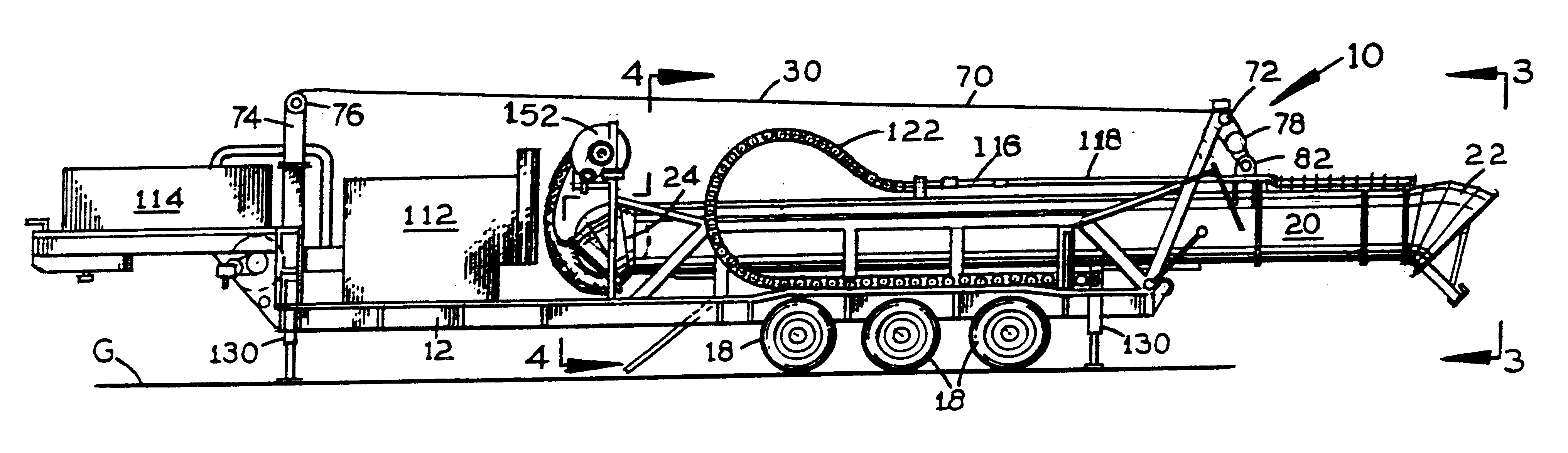
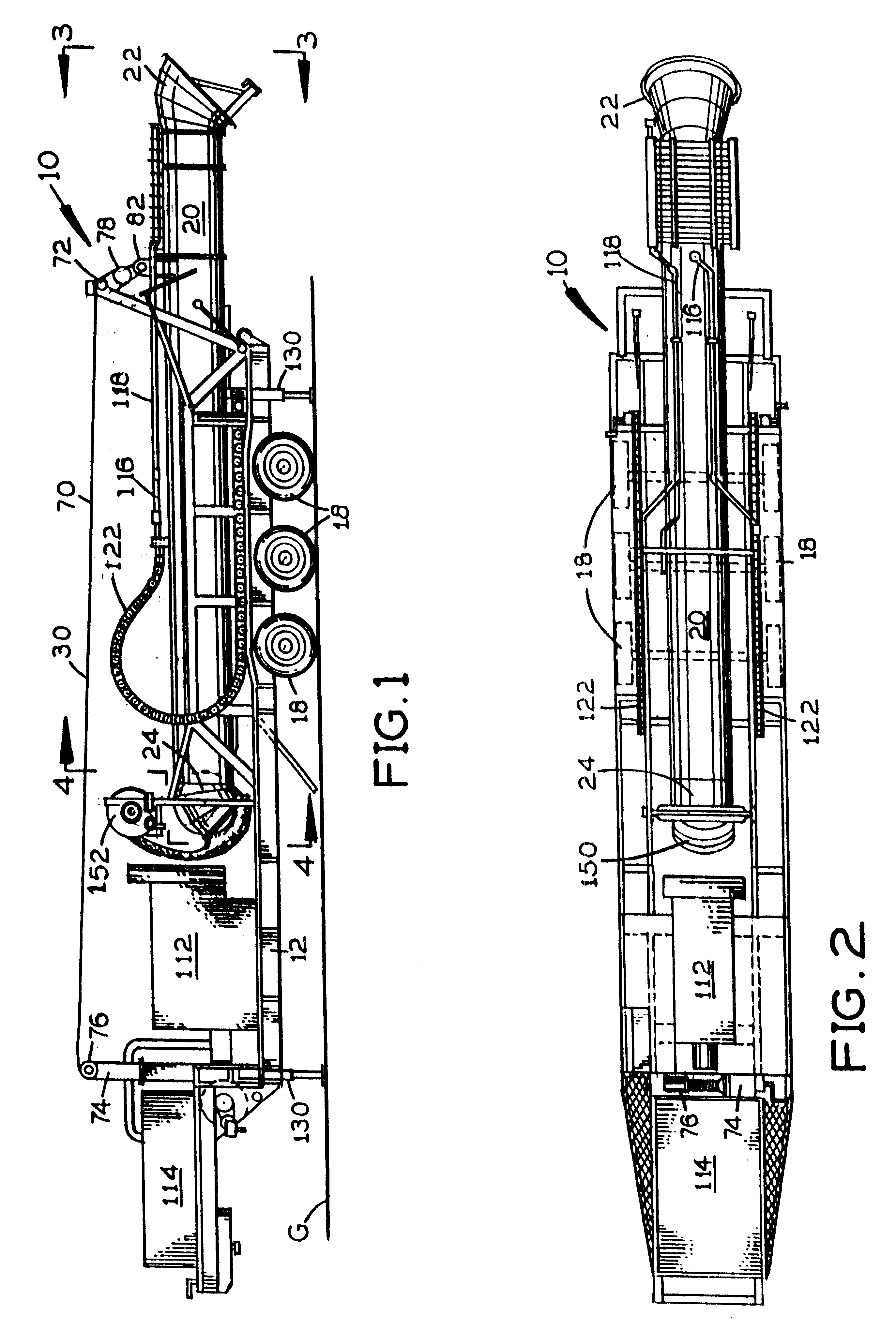
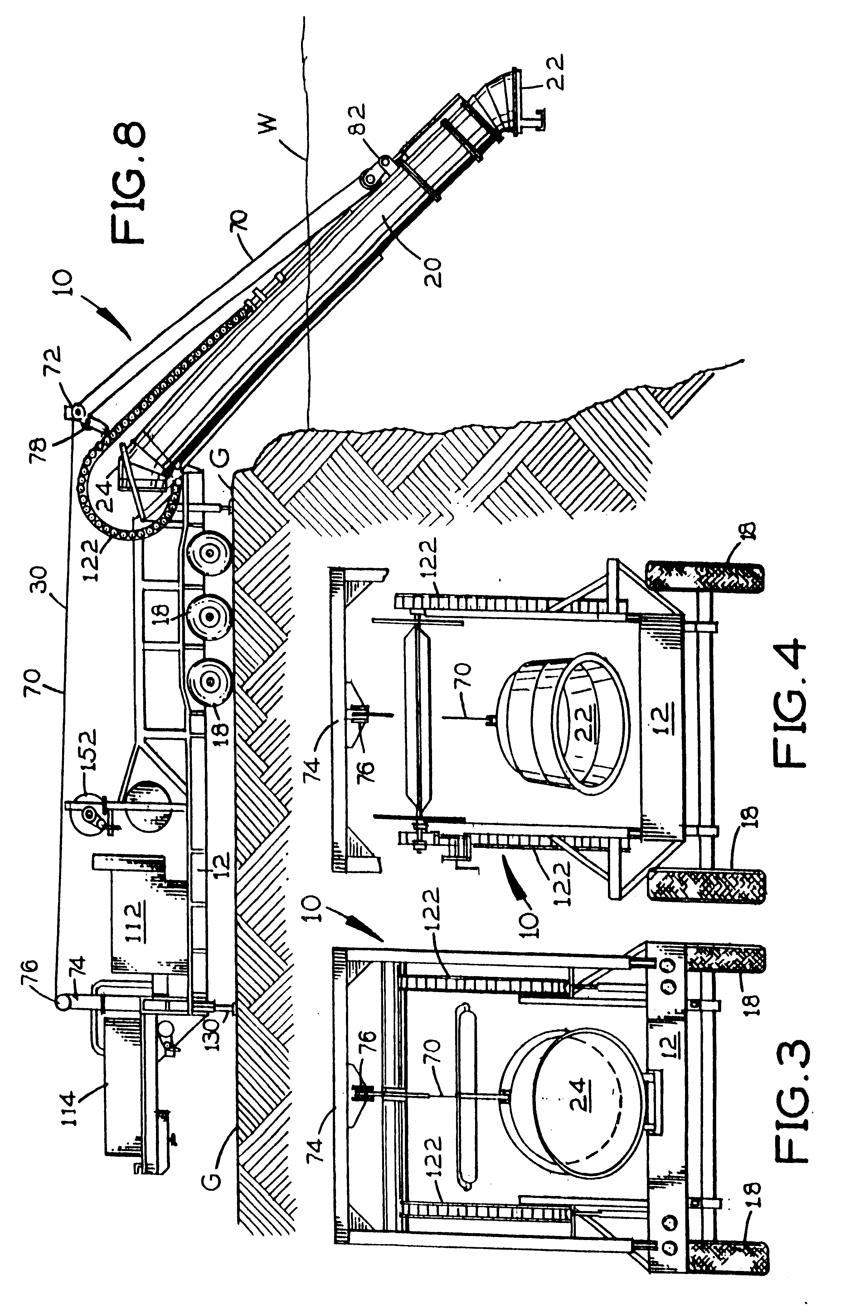
Referring to FIGS. 1-16, a pumping apparatus 10 is disclosed, for drawing water W from a low lying holding area and delivering the water upwardly to and beyond a bank on which apparatus 10 rests to any designated receiving area or means. The contents of U.S. Pat. No. 3,270,677 issued on Sep. 6, 1966 to the present applicant is incorporated by reference into the present application.

Apparatus 10 includes an apparatus base 12 such as a trailer bed and includes a water drawing pipe 20 having a pipe intake end 22 and having a pipe discharge end 24 containing an impeller 102 drivably connected to a hydraulic motor 110 with an impeller drive shaft 104 riding on drive shaft bearings 108, the hydraulic motor 110 receiving pressurized hydraulic fluid through a flexible hydraulic supply hose 116 extending along the drawing pipe 20 from the output side of a hydraulic pump 112 and the hydraulic motor 110 releasing hydraulic fluid into a flexible return hose 118 extending along the drawing pipe 2...


PUM


Abstract

A pumping apparatus for delivering water upwardly from a holding area and over a holding area bank includes an apparatus base; a water drawing pipe having a pipe intake end and a pipe discharge end and being mounted to the apparatus base and extendable from the apparatus base; an impeller rotatably mounted within the drawing pipe discharge end; a hydraulic motor drivably connected to the impeller at the drawing pipe discharge end; a hydraulic pump having a pump intake side and a pump output side; a flexible hydraulic supply hose connected to the pump output side and extending along the drawing pipe to the hydraulic motor; a flexible hydraulic return hose extending from the hydraulic motor along the drawing pipe to the pump intake side; a segmented hose track having a longitudinal track passageway through which the supply and return hoses extend and having a minimum bend radius great enough to prevent the supply and return hoses from kinking.

Description

1. Field of the InventionThe present invention relates generally to the field of pumping mechanisms. More specifically the present invention relates to a pumping apparatus for drawing water from a low lying holding area and delivering the water upwardly and over the bank of the holding area to any designated receiving area or means. The apparatus includes an apparatus base such as a trailer bed and including a water drawing pipe having a pipe intake end and having a pipe discharge end containing an impeller drivably connected to a hydraulic motor which receives pressurized hydraulic fluid through a flexible hydraulic supply hose extending along the drawing pipe from the output side of a hydraulic pump and the hydraulic motor releasing hydraulic fluid into a flexible return hose extending along the drawing pipe to the intake side of the hydraulic pump, a deployment and angling cable means which moves the drawing pipe between a retracted position on the apparatus base and a deployed p...

Claims


Application Information

Patent Timeline
Patent Type & Authority Patents(United States)
IPC IPC(8): F04D29/00E03B3/04E03B3/00F04D29/70
CPCF04D29/708E03B3/04
Inventor ELLER, JAMES DAVIDELLER, DANA J.ELLER, DARREN J.
Owner ELLER JAMES DAVID
Why Eureka
Try Eureka