Transparent metallic millimeter-wave window

a millimeter-wave window and transparent technology, applied in waveguide devices, basic electric elements, electrical equipment, etc., can solve the problems of high loss tangent heat generation of windows, insufficient thermal performance of diamond windows designed for cw operation, and high cost of diamond windows

Inactive Publication Date: 2003-02-18
RAYTHEON CO
View PDF4 Cites 9 Cited by
  • Summary
  • Abstract
  • Description
  • Claims
  • Application Information

AI Technical Summary

Benefits of technology

The novel features of the present invention are its use of a periodic metal structure as a high-power microwave window. Metal structures have been used in windows before, but usually in such a way so as not to interfere with the transmission of microwave energy; this is typically done by placing thin metal ribs perpendicular to the incident electric field. The present invention takes a different approach by making a metal structure an integral part of the window, one that strongly interacts with the incident microwave fields. This approach toward window design is considered to be novel and unique.

Problems solved by technology

This problem is particularly acute at millimeter-wave frequencies, where most dielectric materials tend to have high loss tangents.
At high power levels, a window made from a material having a high loss tangent will become extremely hot and may fail if not actively cooled.
While double-disk windows improve upon the performance of single-disk edge-cooled windows, their thermal performance is insufficient to allow megawatt-class gyrotrons designed for CW operation to operate for more than a few seconds at a time.
However, because a disk of sufficient size and thickness for a gyrotron window takes several weeks to grow, and because there are few sources for such disks, diamond windows are very expensive.

Method used


Image

  • Transparent metallic millimeter-wave window
  • Transparent metallic millimeter-wave window
  • Transparent metallic millimeter-wave window

Examples


Embodiment Construction

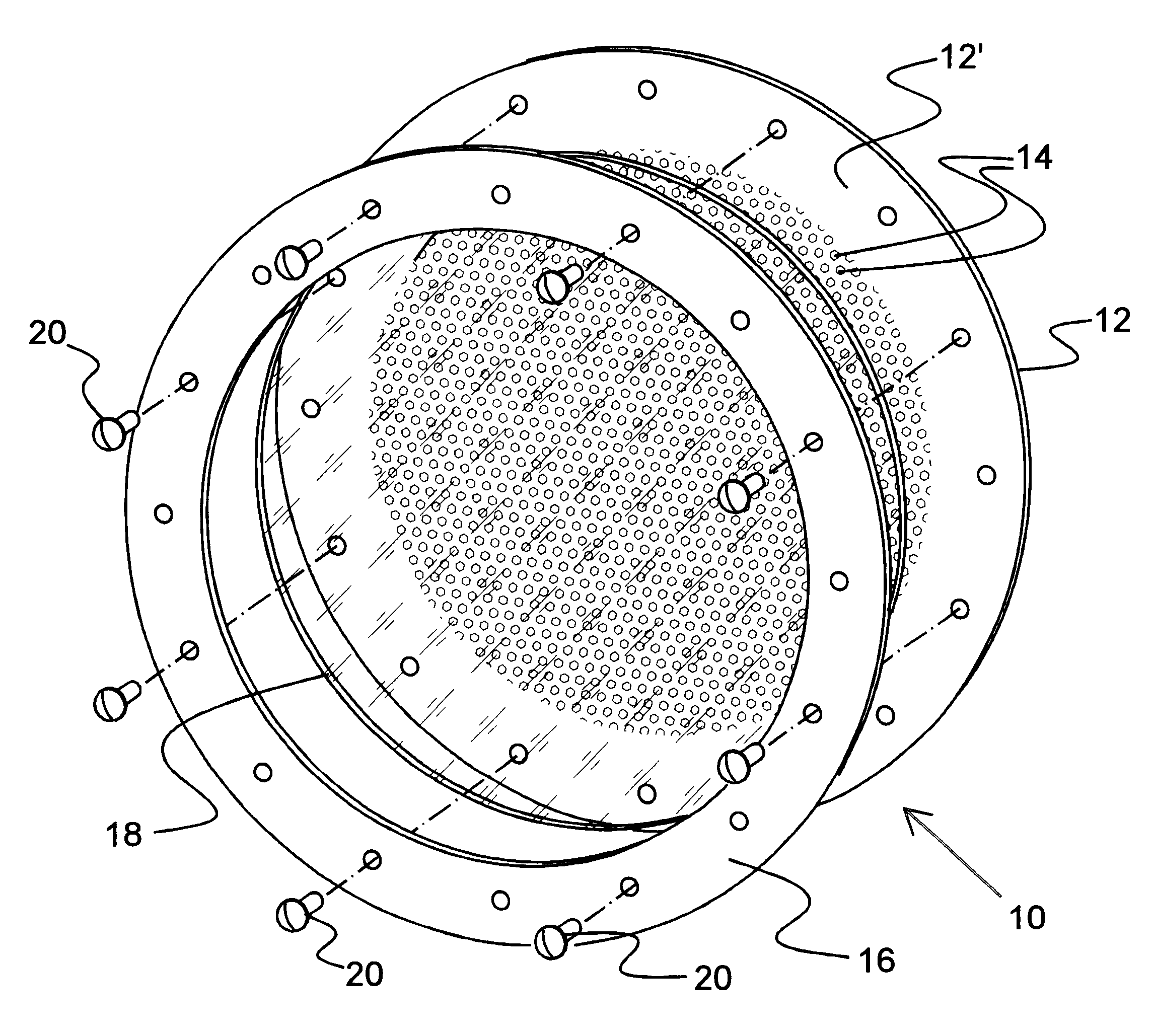
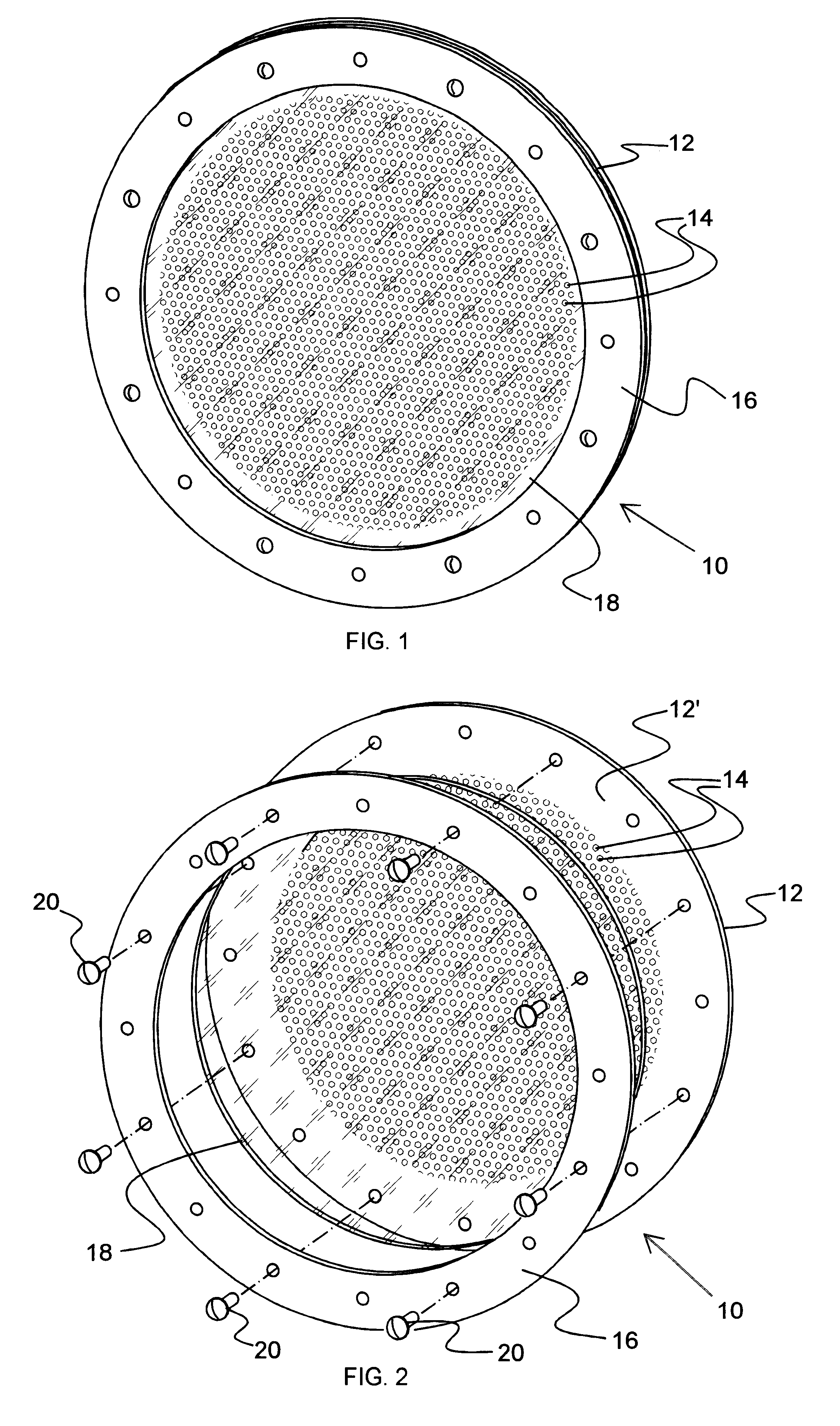
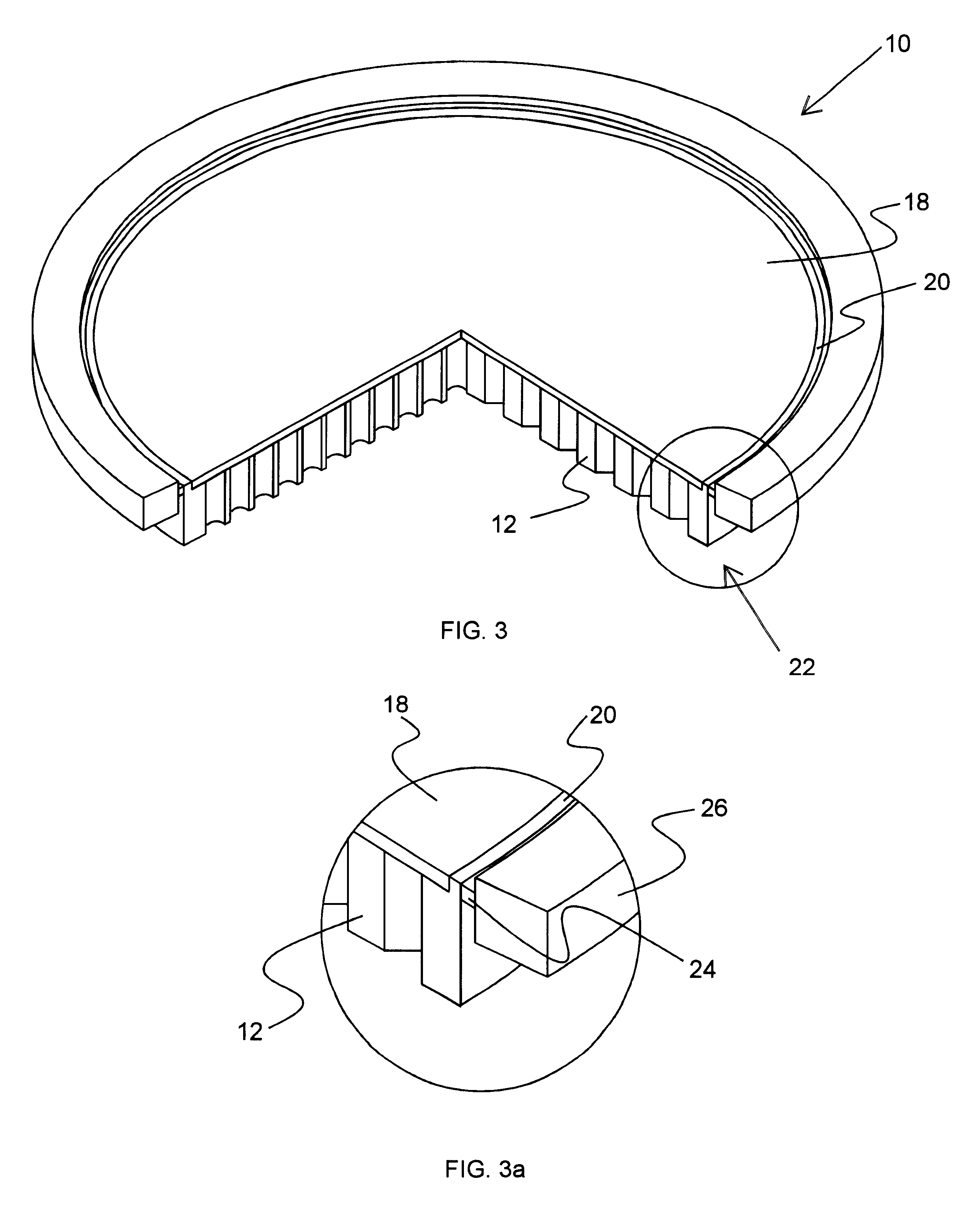
In accordance with the present invention, a transparent metallic millimeter-wave window is provided. The window is constructed from a high conductivity metal, such as copper. One can make a metallic plate transparent over a range of frequencies by perforating it with a periodic array of slots. For the output window of a gyrotron, one might choose an equilateral triangular array of circular holes. By proper choice of the hole spacing and diameter, the window can be made transparent at any desired frequency.

In particular, the present invention is a dielectric-covered metallic window that is transparent at millimeter-wave frequencies. The window is constructed from a metal plate perforated by a periodic array of holes and covered by a thin dielectric plate. The diameter of the holes and the periodicity of the array are chosen to minimize the power reflected at the design frequency. A window constructed to demonstrate the concept is shown in FIG. 1. The window 10 comprises a metal plate...


PUM


Abstract

A millimeter-wave window is constructed from a high conductivity metal plate. The metallic plate is made transparent over a range of frequencies by perforating it with a periodic array of slots. In one embodiment, the millimeter-wave window is used in a gyrotron as the output window. In such a case, one suitable periodic array of slots comprises an equilateral triangular array of slots for operation at 95 GHz. By proper choice of the hole spacing and diameter, the window can be made transparent at any desired frequency. In addition to being transparent, however, the window must also be vacuum tight, as the pressure inside a gyrotron is on the order of 10-9 torr. The present invention solves this problem by covering the surface of the window with a thin layer of a suitable dielectric material, such as fused quartz.

Description

The present invention is related generally to microwave systems, and, more particularly, to transparent high-power windows used in the millimeter region.Microwave systems often require windows that are transparent at the frequencies of interest. This problem is particularly acute at millimeter-wave frequencies, where most dielectric materials tend to have high loss tangents. At low power levels, a high loss tangent may be acceptable, as long as the window is thin enough to prevent more than a small fraction of the incident power from being absorbed. At high power levels, a window made from a material having a high loss tangent will become extremely hot and may fail if not actively cooled. Such windows are usually cooled at their edges, since most coolants themselves have high loss tangents and therefore cannot be directly exposed to millimeter-wave power. The need therefore exists for a microwave window capable of reliably transmitting extremely high levels of millimeter-wave power....

Claims


Application Information

Patent Timeline
Patent Type & Authority Patents(United States)
IPC IPC(8): H01P1/08
CPCH01P1/08
Inventor CROUCH, DAVID D.BROWN, KENNETH W.DOLASH, WILLIAM E.
Owner RAYTHEON CO
Why Eureka
Try Eureka