
Data sequence generator, transmitter, information data decoder, receiver, transmitter-receiver, data sequence generating method, information data decoding method, and recording medium

a data sequence and data decoding technology, applied in the field of data sequence generators, can solve the problems of inability to detect a synchronous position, inability to decode the whole frame, and inability to detect the synchronous position,

Inactive Publication Date: 2003-02-18
KOKUSA ELECTRIC CO LTD
View PDF9 Cites 96 Cited by
  • Summary
  • Abstract
  • Description
  • Claims
  • Application Information

AI Technical Summary

Problems solved by technology

Both the above-mentioned phenomena each are a frame synchronization error of a kind, and when such a frame synchronization error occurs, the receiver side cannot decode the whole frame for which a correct synchronous position has not been obtained and the frame comes to be discarded.
However, in an environment where a burst error occurs (burst error environment), the probability of occurrence of non-detection cannot be reduced even by using the second frame synchronization method.
The reason is that it is impossible to detect a synchronous position in case that the unique word and header information in a frame are contained in a burst error section.
In the HDLC procedure, in case that header information cannot be correctly decoded due to a transmission channel error, the whole frame cannot be decoded in the same way as the case that a frame synchronization error has occurred.
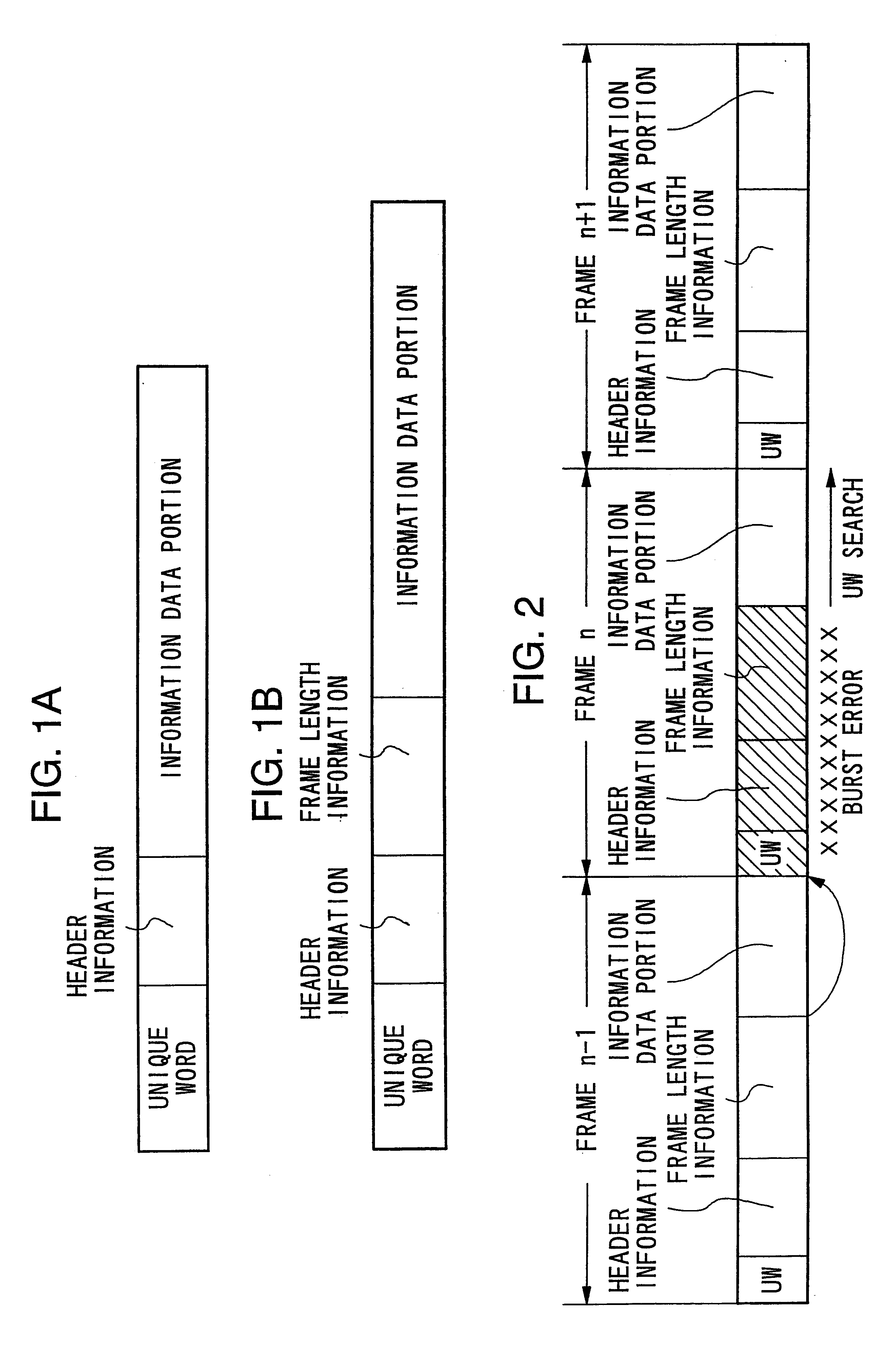
However, in case that an error exceeding the error correcting ability of the header information has occurred in the header information portion in a frame as shown in FIG. 2, even if the header information has been error-correction-encoded, since although a frame-synchronous position can be determined as described above the header information cannot be decoded, the information data cannot be decoded and the frame results in being discarded.
In order to improve the whole error resiliency of a frame it is conceivable to apply an error correction code having a high error correction ability, but in a burst error environment a robust error correction ability coping with densely occurring errors becomes necessary and the redundancy of transmission data results in being greatly increased.
However, this method requires that the positions of data transmitted separately at plural times have been determined in advance, and it cannot be applied to transmission of such data whose position cannot be determined as the header information in a variable length frame.
And in a random error environment having a high code error rate, when an error occurs in any data separately and repeatedly sent at plural times even if those errors are small in number, it is no longer possible to normally receive the data.
Although it is of course conceivable to error-correction-code each of the data to be sent separately and repeatedly at plural times, when attempting to obtain a sufficient error correction ability, eventually the redundancy of transmission data becomes great and the transmission efficiency of data is greatly deteriorated in cooperation with the redundancy of sending separately and repeatedly the data at plural times.
As described above, according to a variable length data transmission system adopting a former frame synchronization method, it has been difficult to satisfactorily perform at the same time the synchronization of a variable length frame and the protection of such important information as header information and the like in a transmission channel having a high code error rate.
Since these plural pieces of header information are arranged separately from one another, the possibility that an error occurs in every piece of header information is low even if a burst error occurs in a transmission channel.

Method used


Image

  • Data sequence generator, transmitter, information data decoder, receiver, transmitter-receiver, data sequence generating method, information data decoding method, and recording medium
  • Data sequence generator, transmitter, information data decoder, receiver, transmitter-receiver, data sequence generating method, information data decoding method, and recording medium
  • Data sequence generator, transmitter, information data decoder, receiver, transmitter-receiver, data sequence generating method, information data decoding method, and recording medium

Examples


first embodiment

A. First Embodiment

A variable length data transmission system having a transmitter and a receiver according to a first embodiment of the present invention is described.

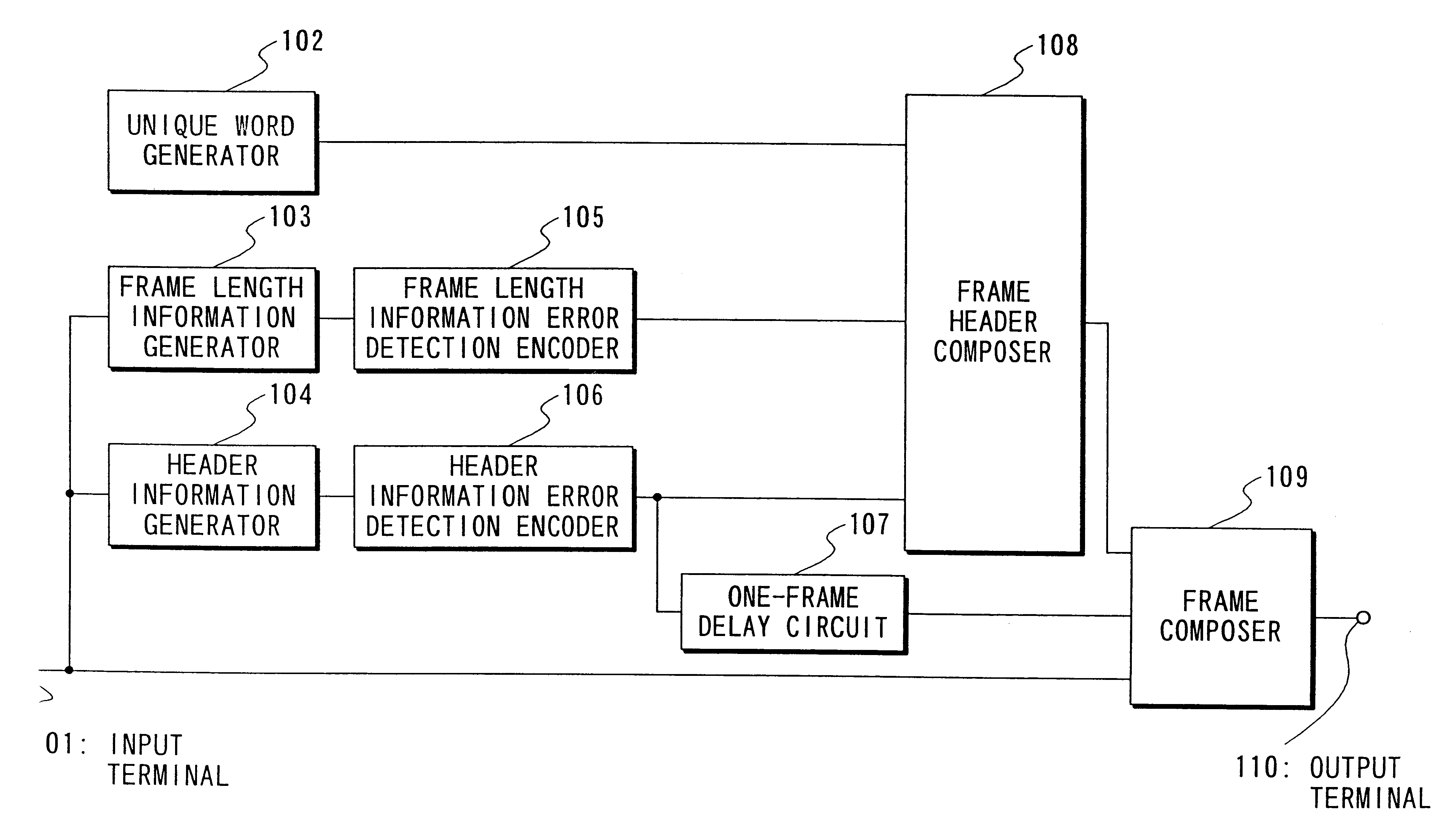
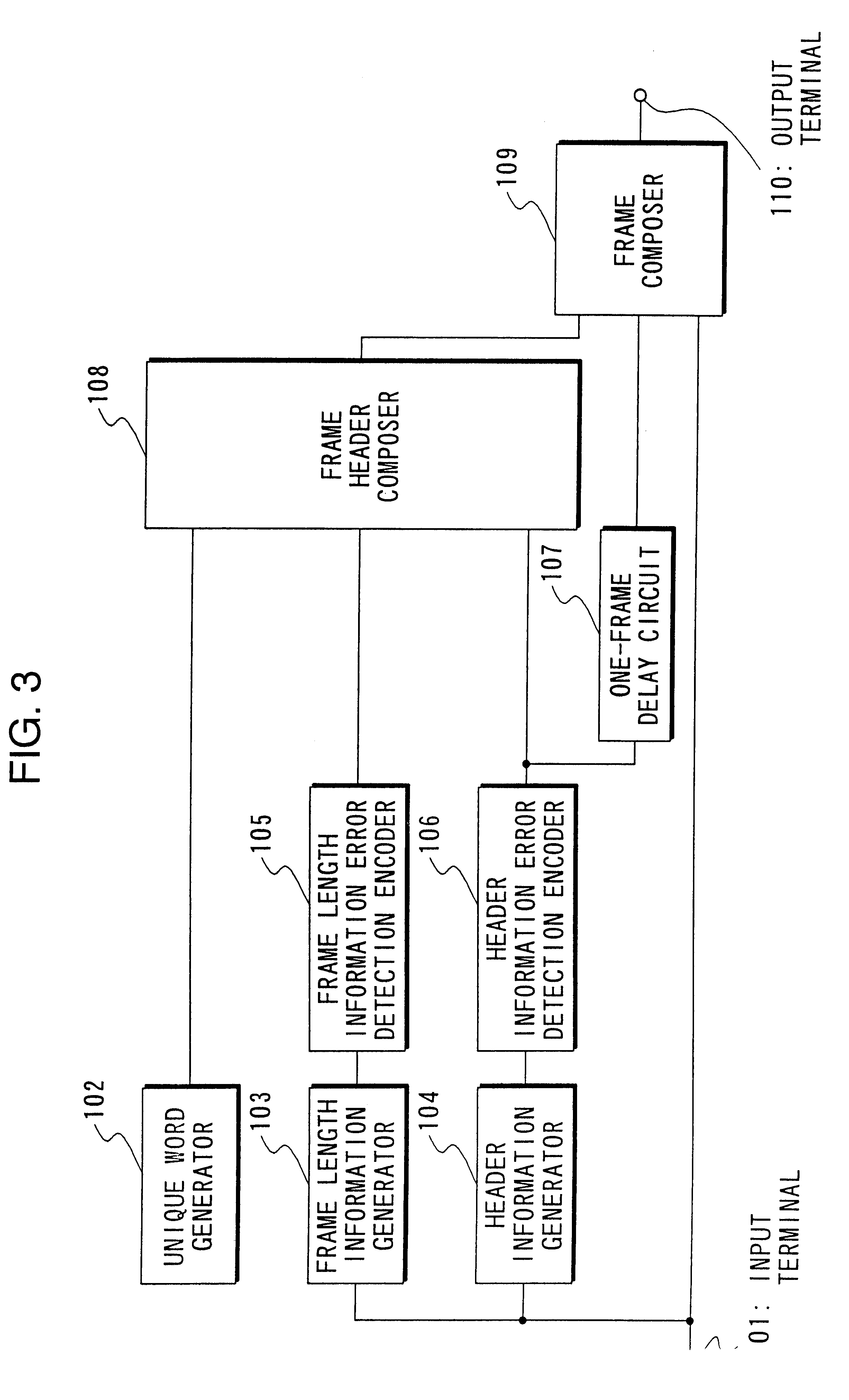
The same system fundamentally, in a data sequence generator inside the transmitter, composes a frame by adding a unique word (UW: specific information), header information and frame length information to information data to be transmitted and distributively arranges the header information in the frame or another frame, and in an information data decoder inside the receiver, establishes a frame synchronization by means of a frame synchronization method using detection of a unique word and error detection of header information and a frame synchronization using frame length information, and decodes the frame information on the basis of the correctly decoded header information out of distributively arranged pieces of header information.

A-1. Composition

First, the composition of the same system is described with reference t...

second embodiment

B. Second Embodiment

A variable length data transmission system having a transmitter and a receiver according to a second embodiment of the present invention is described.

The same system has basically the same function as the system according to the first embodiment, but is different from the system according to the first embodiment only in a fact that an error detection encoding process and an error correction encoding process are applied to one piece of header information to be used for establishing a frame synchronization out of two pieces of header information contained in one frame and to the frame length information, and only an error detection encoding process is applied to the other piece of header information. Therefore, description of the portions common to the first embodiment is omitted in the following description.

B-1. Composition

First, the composition of the same system is described with reference to FIGS. 11 to 14. FIG. 11 is a block diagram showing a data sequence gen...

example 1

B-4. Variation Example 1

FIG. 15 is a diagram showing the frame structure of a variable length frame to be transmitted in a variation example 1 of the same system, and this frame structure is different from the frame structure shown in FIG. 13 only in a fact that only an error detection encoding process is applied to frame length information.

FIG. 16 is a block diagram showing the composition of a data sequence generator in the same variation example, and this composition is different from the composition shown in FIG. 11 in that a frame length information error detection encoder 305a is provided in place of the header information and frame length information error detection and error correction encoder 305, that a header information error correction encoder 305b is provided in parallel with the one-frame delay circuit 307 at a stage following after the header information error detection encoder 306, and that output of the header information generator 304 is inputted only into the hea...


PUM


Abstract

The probability of frame destruction is lowered while suppressing the redundancy of the transmission data. On the transmitting side, a predetermined unique word is contained in a frame n for storing the n-th data, and header information n, frame length information and header information n-1 of the frame n-1 one frame before the frame n are subjected to error-correcting coding, contained in the frame n, and transmitted. On the receiving side, the header of the frame n is received. When the frame length information is transmitted with error, the timing is specified by detecting the unique word and header information in the next frame n+1. When the header of the frame n is not successfully decoded, the information data of the frame n is decoded by using the header information n inserted into a predetermined position of the frame n+1.

Description

1. Field of the InventionThe present invention relates to a data sequence generator for generating a data sequence suitable for transmission of a data sequence composed of variable length frames having information data of variable length particularly in an environment where a code error is liable to occur, a transmitter using the data sequence generator, an information data decoder for decoding information data from the data sequence, a receiver using the information data decoder, a transmitter-receiver using the data sequence generator and the information data decoder, a data sequence generating method for generating the data sequence, an information data decoding method for extracting information data from the data sequence, and a recording medium recording the data sequence.2. Description of the Related ArtIn case of transmitting a data sequence having a frame structure, detection of the synchronous position of a frame in a received signal sequence, namely, a frame synchronizatio...

Claims


Application Information

Patent Timeline
IPC IPC(8): G11B20/18G11B20/12G11B27/10G11B27/30H04L1/08H03M13/09H03M13/00
CPCG11B20/12G11B20/1217G11B20/1833G11B27/10H04L1/08H03M13/09H04L1/0072H04L1/008G11B27/3027H04L1/00
Inventor SUZUKI, TAKASHIMIKI, TOSHIOKAWAHARA, TOSHIRONAKA, NOBUHIKO
Owner KOKUSA ELECTRIC CO LTD
Learn More