Measuring system

a technology of measuring system and sensor guide, which is applied in the direction of tension measurement, force/torque/work measurement apparatus, instruments, etc., can solve the problems of soiling of the sensor and the sensor guide, increasing the difficulty of accessibility and accuracy, and affecting the accuracy of the measuremen

Inactive Publication Date: 2003-02-25
VOITH PATENT GMBH
View PDF6 Cites 6 Cited by
  • Summary
  • Abstract
  • Description
  • Claims
  • Application Information

AI Technical Summary

Benefits of technology

The positions of the sensor and sensor guide are naturally to be regarded in connection with one another, the sensor should be allowed the best possible protection from soiling in the interests of measuring accuracy. Here, the placement of the sensors in the sensor guide could also be advantageous.
It is further advantageous here for the sensor preferably to be arranged together with the sensor guide on the web exit side of the lower roll. This simplifies the insertion of the fibrous material web and the transfer of a strip of it and reduces the danger of soiling.
Nevertheless, the sensor and the sensor guide should be protected from soiling by deflecting plates or the like. Furthermore, it is advantageous for the sensor guide to be structured in such a way that it allows a movement of the sensor across the width of the fibrous material web at least on one side of the machine, preferably past the rolls. This makes it possible for the sensor to be moved into the areas of the fibrous material web in danger of soiling only for measuring. The ability of the sensor to be moved past the rolls allows its maintenance and cleaning even while the machine is in operation.
In accordance with yet another feature of the instant invention, a doctor can be arranged against the surface of at least one upper roll, and at least one sensor may be arranged so that materials removed by the doctor do not soil the sensor(s).

Problems solved by technology

Because of the high speeds, supporting the fibrous material web in these machines with a belt or a roll is indispensable, which makes measurement even more difficult with respect to accessibility and accuracy.
Furthermore, in stationary measuring systems, considerable problems result from the soiling of the sensor and the sensor guide.
Added to this is the difficult accessibility for cleaning and maintenance.

Method used


Image

  • Measuring system
  • Measuring system

Examples


Embodiment Construction

The particulars shown herein are by way of example and for purposes of illustrative discussion of the embodiments of the present invention only and are presented in the cause of providing what is believed to be the most useful and readily understood description of the principles and conceptual aspects of the present invention. In this regard, no attempt is made to show structural details of the present invention in more detail than is necessary for the fundamental understanding of the present invention, the description taken with the drawings making apparent to those skilled in the art how the several forms of the present invention may be embodied in practice.

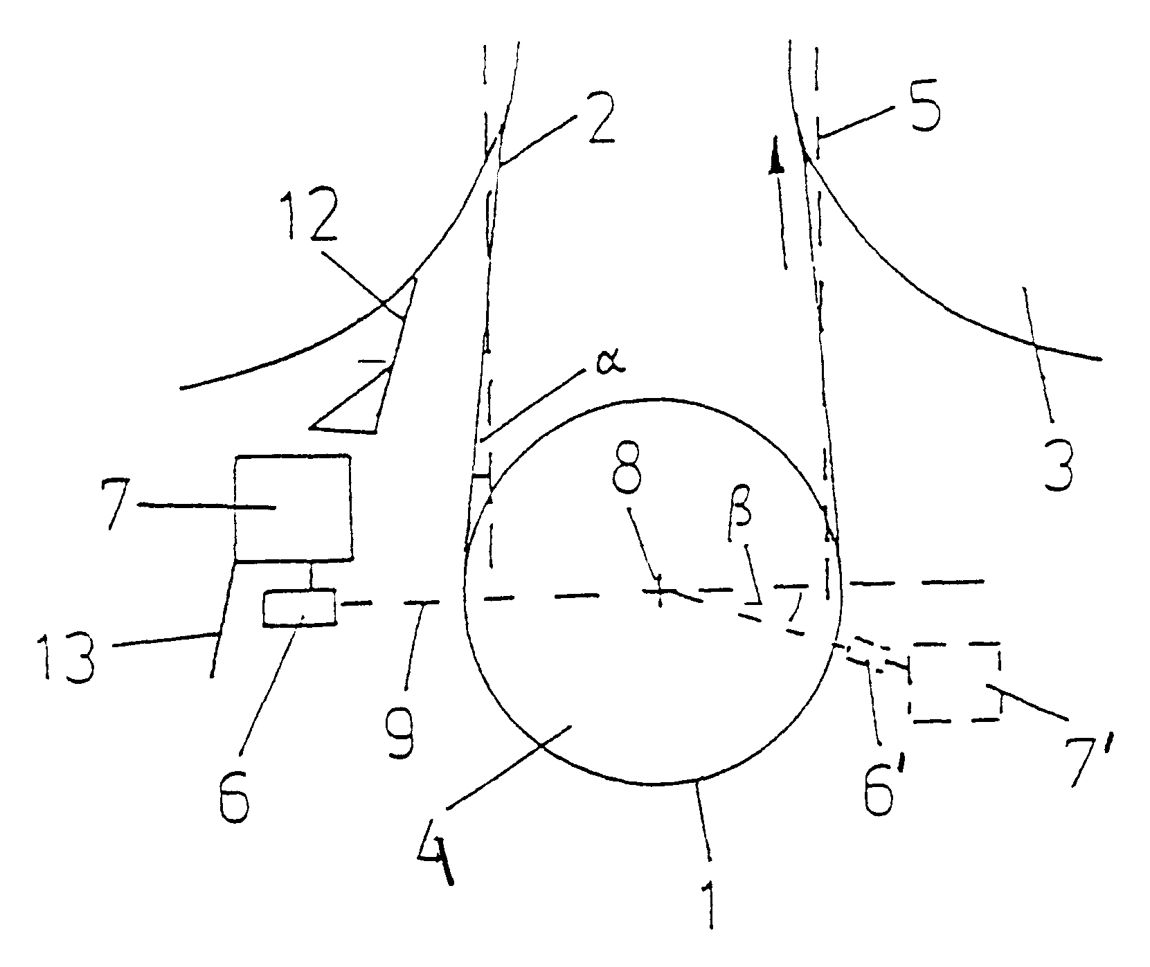
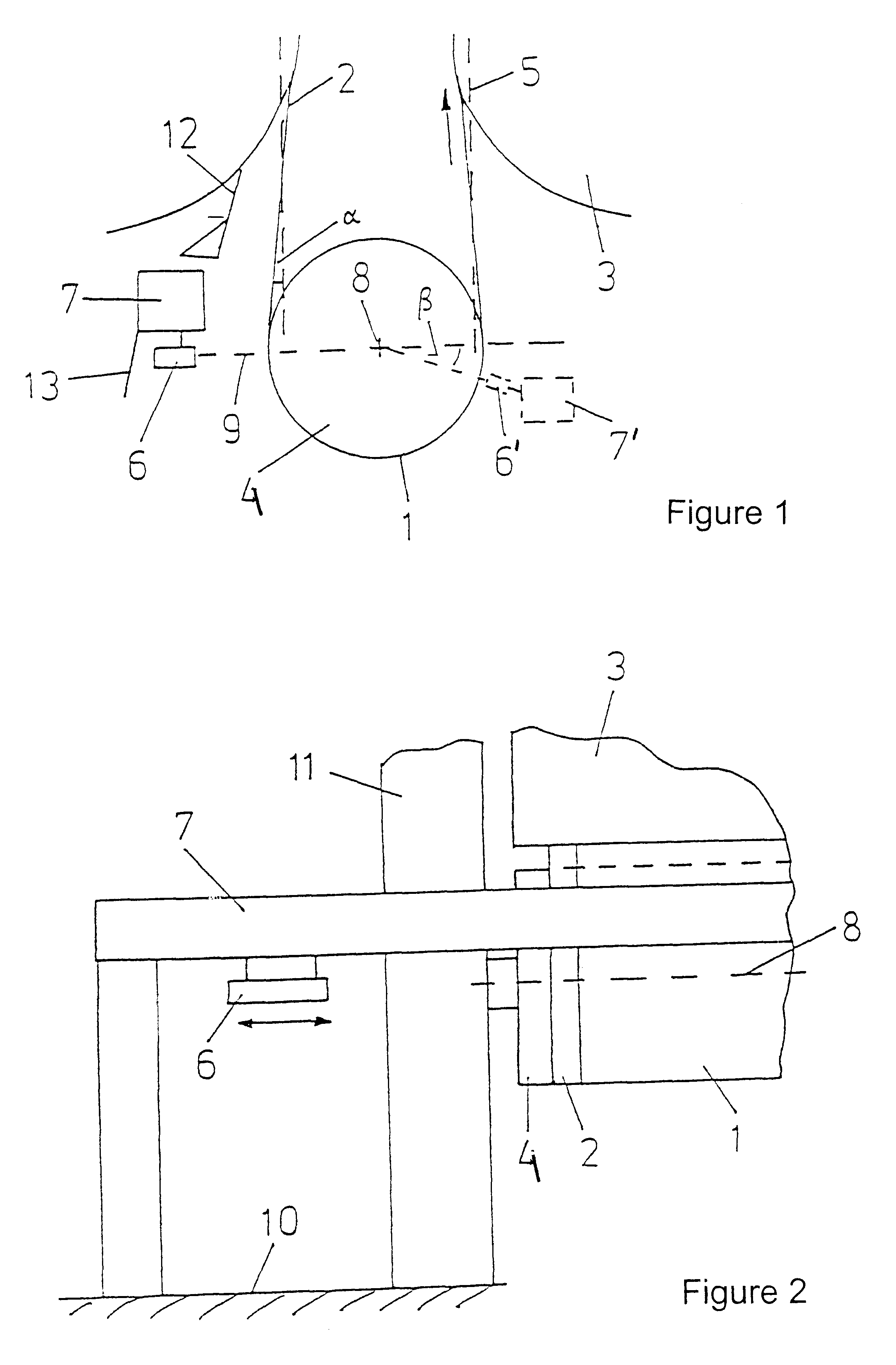
The drying section includes two rows of rolls 3, 4, with the upper rolls 3 being embodied as heated drying cylinders and the lower rolls 4 being embodied as suctioned guide rolls. The suctioned guide rolls have a perforated roll jacket whose inner chamber is connected to a vacuum source. In order to dry the fibrous material web...


PUM

PropertyMeasurementUnit
angleaaaaaaaaaa
angleaaaaaaaaaa
angleaaaaaaaaaa

Abstract

Measuring system and process for determining properties of a running fibrous material web in a drying section of a machine producing the fibrous material web. The system includes at least one upper roll and at least one lower roll. The fibrous material web is arranged to partially wrap the at least one upper roll and the at least one lower roll and to run between these rolls at an angle between about 0 and 45° to a vertical. A sensor guide is arranged crosswise to a web run direction, and at least one sensor is arranged to traverse the sensor guide in the web run direction in a region of the at least one lower roll. The sensor is structured and arranged for determining a web parameter, and is oriented to form a maximum angle of about 60° to a horizontal through an axis of the lower roll.

Description

The present application claims priority under 35 U.S.C. .sctn.119 of German Patent Application No. 100 19 568.7, filed on Apr. 20, 2000, the disclosure of which is expressly incorporated by reference herein in its entirety.1. Field of the InventionThe invention relates to a measuring system for determining properties of a running paper, cardboard, tissue, or other fibrous material web, in particular arranged in the drying section of a machine for the production and / or finishing thereof, in which the fibrous material web partially wraps at least one upper and one lower roll and an angle of 0 to 45.degree. to a vertical runs between these rolls, with at least one sensor for detecting a web property being arranged in the region of the lower roll on a sensor guide traversing the fibrous material web in a crosswise manner.2. Discussion of Background InformationIn order to optimize the production and / or finishing process, it is constantly becoming more important to detect the operating co...

Claims


Application Information

Patent Timeline
Patent Type & Authority Patents(United States)
IPC IPC(8): D21F5/00D21G9/00D21F5/04D21F7/00
CPCD21G9/0009D21F5/04
Inventor OECHSLE, MARKUSWEGEHAUPT, FRANK
Owner VOITH PATENT GMBH
Why Eureka
Try Eureka