Laminating device with laminate edge cutting unit

a cutting unit and laminate edge technology, applied in the direction of mechanical control devices, process and machine control, instruments, etc., can solve the problems of excessive wideness of laminate webs, excessive length in the x direction, and excessive thickness of sheets

Inactive Publication Date: 2003-02-25
BROTHER KOGYO KK
View PDF4 Cites 25 Cited by
  • Summary
  • Abstract
  • Description
  • Claims
  • Application Information

AI Technical Summary

Benefits of technology

With this configuration, when the power switch of the laminate device is turned OFF, then the cutter unit is automatically moved to a position to the outside of the width of the laminate. While the cutter unit is in this position, the cutter unit is not positioned in the pathway that the webs are transported through. Therefore, when the webs are exchanged while the cutter unit is in this position, the webs can be set in the laminating apparatus safely and reliably.
With this configuration, when the user rotates the rotary knob to turn the power switch ON and OFF, the reference side cutter is automatically moved via the linking mechanism to the cut position or the retracted position and maintained in that position. As a result, the webs will only be changed while the reference side cutter is in the retracted position, so that web exchange can be safely and reliably performed.
With this configuration, the other side cutter is controlled to move and position in conjunction with the movement and positioning of the reference side cutter. Therefore, operations for setting the webs and for cutting the laminate can be easily achieved.
With this configuration, when the rotary knob is in a power off position, the cutter transport unit moves the reference side cutter and the other side cutter into the retracted position. Therefore, the webs can be set safely and reliably.

Problems solved by technology

Sometimes the laminating webs can be excessively wide with respect to the sheet to be laminated, that is, their length is excessive in the X direction.
Also, the sheet can be too wide compared to the webs, so that the sheet sticks out from between the webs after lamination is complete.
However, conventional devices are not provided with configuration for cutting left, right, or both edges of the laminate, that extend parallel with the transport direction, that is, with the Y directions.
When the blades contact a laminate web, they can interfere with its transport or even damage the laminate web.
The laminate webs need not be installed using a cassette for this potential problem to occur, but could be in an uncovered condition when replenished or exchanged.

Method used


Image

  • Laminating device with laminate edge cutting unit
  • Laminating device with laminate edge cutting unit
  • Laminating device with laminate edge cutting unit

Examples


Embodiment Construction

Next, an explanation of a laminating apparatus according to an embodiment of the present invention will be described while referring to the attached drawings.

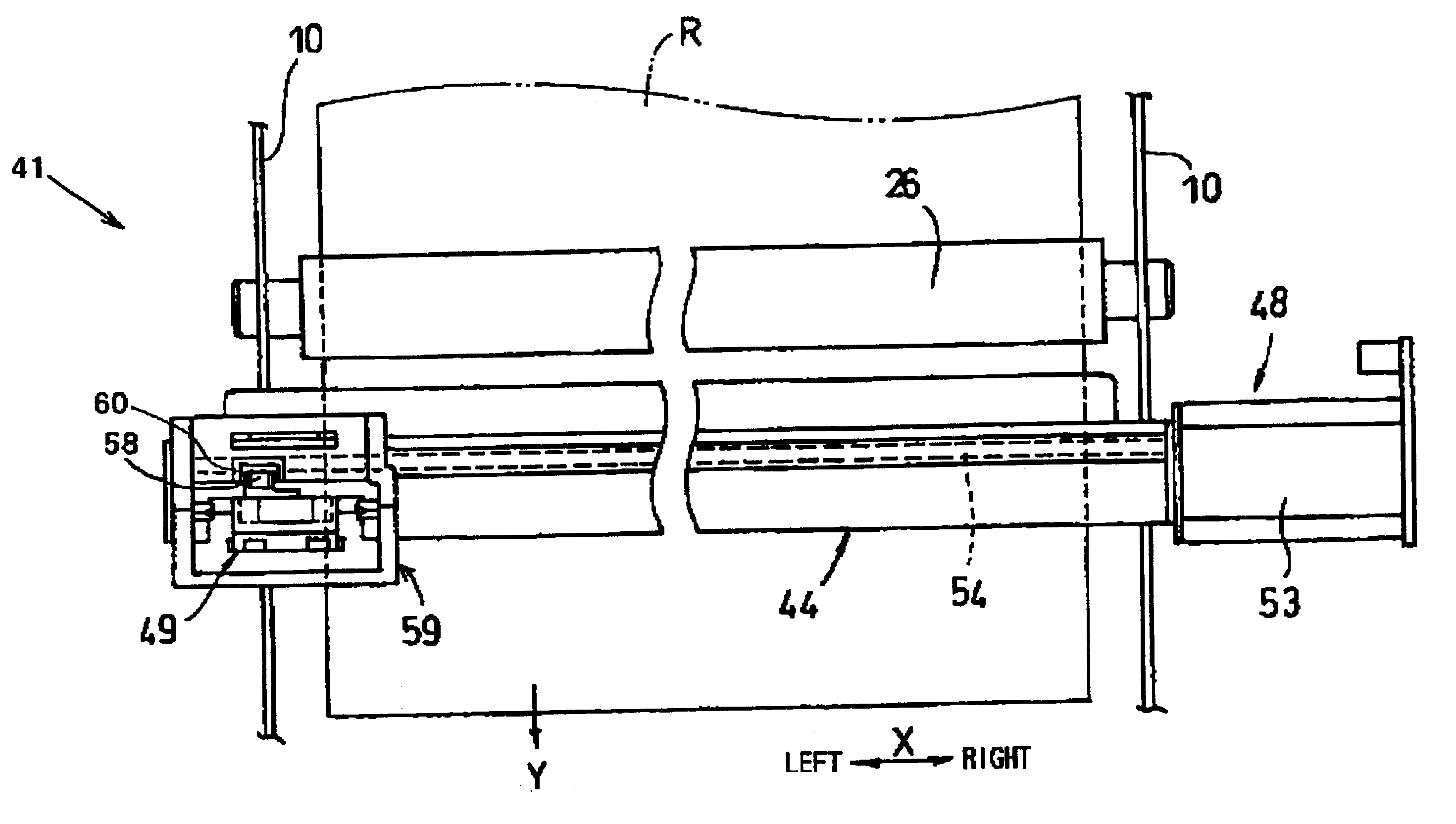
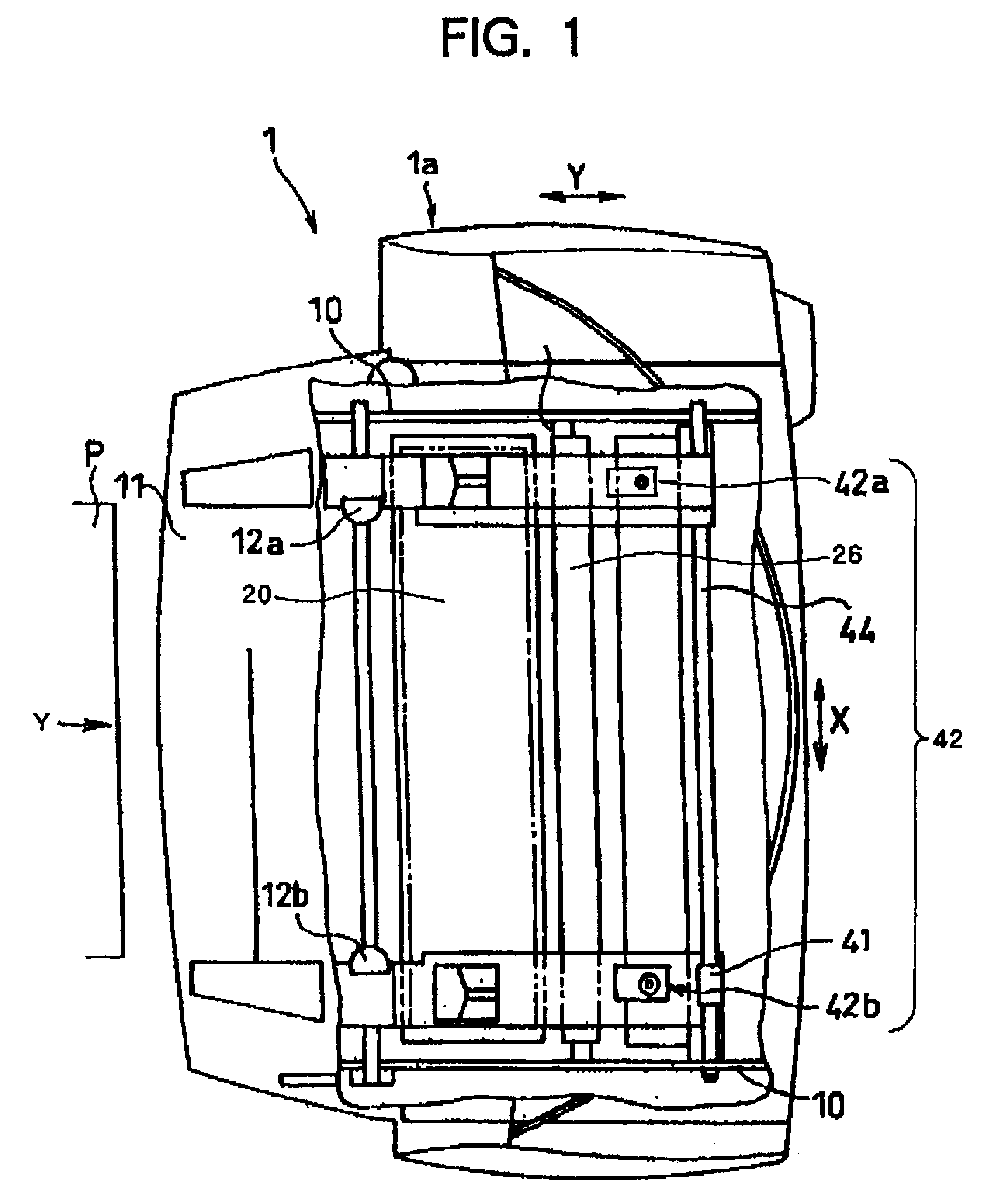
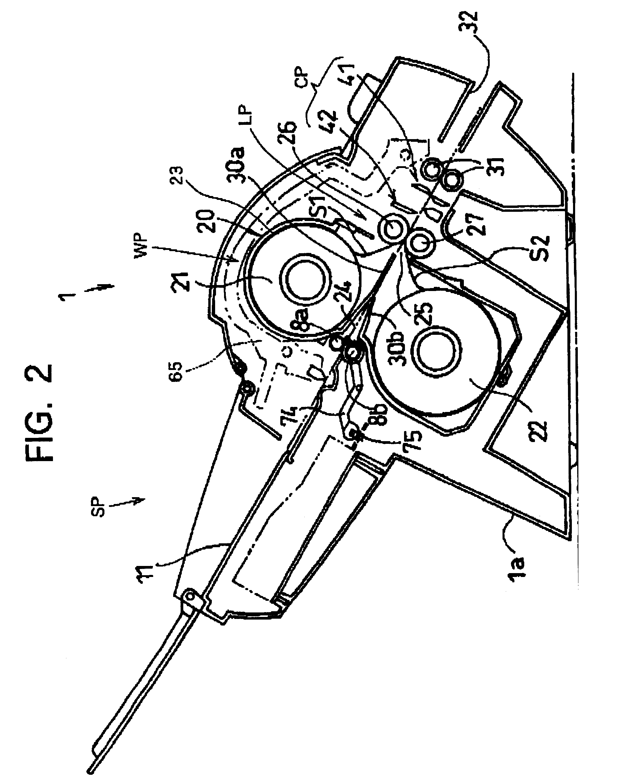
As shown in FIG. 1, a laminating apparatus 1 according to the present embodiment includes a case 1a formed from synthetic resin. As shown in FIG. 2, the laminating apparatus 1 includes a sheet supply portion SP for supplying an sheets P, such as a document or a card represented by sheet P hereinafter, a web supply portion WP for supplying laminating webs S1, S2 for laminating the sheet P, a laminating portion LP that operates to sandwich the sheet P supplied from the sheet supply portion between the webs S1, S2, and a cutting portion CP that cuts the laminate discharged from the laminating portion LP.

As shown in FIGS. 1 and 2, the sheet supply portion SP includes a sheet supply tray 11 and a pair of sheet supply rollers 8a, 8b. The sheet supply tray 11 is disposed at the upper left hand portion of the case 1a as viewed in FIG. ...


PUM

PropertyMeasurementUnit
poweraaaaaaaaaa
widthaaaaaaaaaa
lengthaaaaaaaaaa

Abstract

A reference-side longitudinal cutting unit and an other side longitudinal cutting unit are disposed to move separately to the left and right sides of a laminate to be cut. A cutter 62a of the reference-side longitudinal cutting unit and a rotary knob 80 for turning on, for example, a power switch 82 are connected to a link mechanism 84 for linking pivotal movement of the rotary knob 80. According to the mode selection position of the rotary knob 80, the cutters 62a , 62b are moved into a retracted position when the rotary knob 80 is in the power OFF or no-mode selection positions and move to a longitudinal cutting position when the rotary knob 80 is in the margin or NO-MARGIN mode selection position.

Description

1. Field of the InventionThe present invention relates to laminating device for adhering a synthetic resin web to both upper and lower surfaces of a sheet-shaped object.2. Description of the Related ArtThere has been a laminating device for laminating a synthetic resin web, for example, onto a card or other sheet-shaped object.Japanese Patent-Application Publication No. HEI-10-507005 discloses a laminating apparatus with a transfer apparatus, a web cartridge detachably fitted in the transfer apparatus, and a feed tray detachably mounted in the web cartridge.The web cartridge includes upper and lower feed rolls. Each feed roll contains a wound up web of web, such as pet web. One feed tool is disposed above the feed tray and the other fed tool is disposed below the feed tray.The transfer apparatus includes upper and lower nip rollers disposed at the sheet-discharge side of the web cartridge, and an external crank handle for rotating the nip rollers in synchronization when turned. The ...

Claims


Application Information

Patent Timeline
Patent Type & Authority Patents(United States)
IPC IPC(8): B32B37/22B32B37/14B26D1/24B29C63/02B26D5/06
CPCB32B37/226B32B38/0004Y10T156/1084B32B38/105
Inventor KUKI, MASAKAZU
Owner BROTHER KOGYO KK
Why Eureka
Try Eureka