Arrangement for recovering spacecraft

a spacecraft and arrangement technology, applied in the field of arrangement for recovering spacecraft, can solve the problems of affecting or endangering the optimal operation, defective spacecraft may have a negative influence, and interfere with these other systems,

Inactive Publication Date: 2003-02-25
AIRBUS DEFENCE & SPACE
View PDF12 Cites 88 Cited by
  • Summary
  • Abstract
  • Description
  • Claims
  • Application Information

AI Technical Summary

Benefits of technology

In the retracted condition, the spreader arms are pivoted relatively radially inwardly toward the extension axis of the holder element. On the other hand, in the extended condition, the spreader arms are spread radially outwardly from the extension axis of the holder element, so as to engage into a corresponding interface ring provided on the second spacecraft, i.e. the spacecraft to be recovered. In the deployed, extended or spread-out condition, the spreader elements reach and engage into a recess and / or behind an overhanging rim of the interface ring so as to establish especially a tension-transmitting connection. A spring arrangement braces against the second satellite, especially in a direction parallel to the lengthwise axis of the holder element, for fixing the spreader elements into the interface ring by means of an elastic spring-biased bracing effect.
The invention provides a simple embodiment of a capture and arresting apparatus, for achieving a coupling of a recovery craft to a spacecraft that is to be recovered. In comparison to conventional recovery systems using grippers or other coupling means, the inventive coupling system has the advantage of a mechanically simple and thus trouble-free and interference-free construction.
In order to achieve a good adaptation and compensation of a rather large range of deviations or mis-alignments between the two spacecraft, the invention provides that the coupling head including the spreader elements is essentially self-centering and self-aligning in the interface ring, and that a large distance between the two spacecraft can be bridged and coupled because the mast-like holder element comprises an extendable telescoping pipe. The telescoping action of the inner pipe and outer pipe can also automatically pivotally spread out and thereby deploy the spreader elements that couple into engagement with the interface ring.
To ensure a well-controlled positioning and coupling of the coupling head into the interface ring, the holder element is initially rigidly connected to the recovery craft by a releasable rigid mount. On the other hand, in order to decouple the body dynamics of the two spacecraft from each other, the rigid mount is released from the recovery craft after the coupling connection has been established. Thereby, the holder element is no longer rigidly mounted or connected to the recovery craft. Instead, an extendable cable arrangement or the like provides a flexible tension-transmitting connection between the coupling arrangement and the recovery craft, without transmitting any forces other than direct tension forces. To achieve a simple release or decoupling, the connection of the holder element to the recovery craft can be provided by pyrotechnically explodable bolts or the like, or any releasable connectors.

Problems solved by technology

Recovery measures are necessary when the position and orbit or trajectory of the defective or expended spacecraft would possibly impair or endanger the optimal operation of some other spacecraft or space system.
A defective spacecraft may have a negative influence on other spacecraft or satellite systems, for example, if the defective satellite has not reached its original intended target position in an intended orbit, or has drifted out of that intended position, and as a result, the defective satellite is positioned in a reception and transmission zone of other systems and thus interferes with these other systems through its electro-magnetic characteristics or a simple shading effect.
Recovery measures are also necessary if a spacecraft is in a decaying orbit and will re-enter the earth's atmosphere in a manner whereby parts of the spacecraft, which have not completely burned-up in the earth's atmosphere, will crash or impact onto the earth in inhabited areas, thereby possibly endangering persons and property.
In other words, a dangerous uncontrolled partial incineration of the defective spacecraft in the earth's atmosphere arises if the spacecraft follows a re-entry path with an improper re-entry angle, so that a complete burning-up or incineration of the spacecraft in the atmosphere cannot be achieved.
In this case, it is possible that the spacecraft or parts thereof will impact the earth at an undesired impact location, which would endanger persons and property.
It has been found in practice, that it is rather complicated and costly to capture, recover and transport-away defective spacecraft or spacecraft that have reached the end of their service life, such as rocket parts, burned-out rocket stages, satellites, space station elements and the like.
Previously it has not been possible to recover and transport spacecraft that are themselves not maneuverable, without direct human intervention and active control.
It has been especially difficult to achieve the actual capture and coupling of the defective or expended spacecraft to the recovery craft.
The known coupling measures require complex, high-precision positioning and engagement of the respective coupling means, which is rather difficult to achieve in practice.
It is not possible to achieve coupling in the event of substantial deviations or distances between the two spacecraft.
The disclosed arrangement is not suitable for taking up and transmitting substantial tension forces between the two spacecraft.
Thereby, the holder element is no longer rigidly mounted or connected to the recovery craft.

Method used


Image

  • Arrangement for recovering spacecraft
  • Arrangement for recovering spacecraft
  • Arrangement for recovering spacecraft

Examples


first embodiment

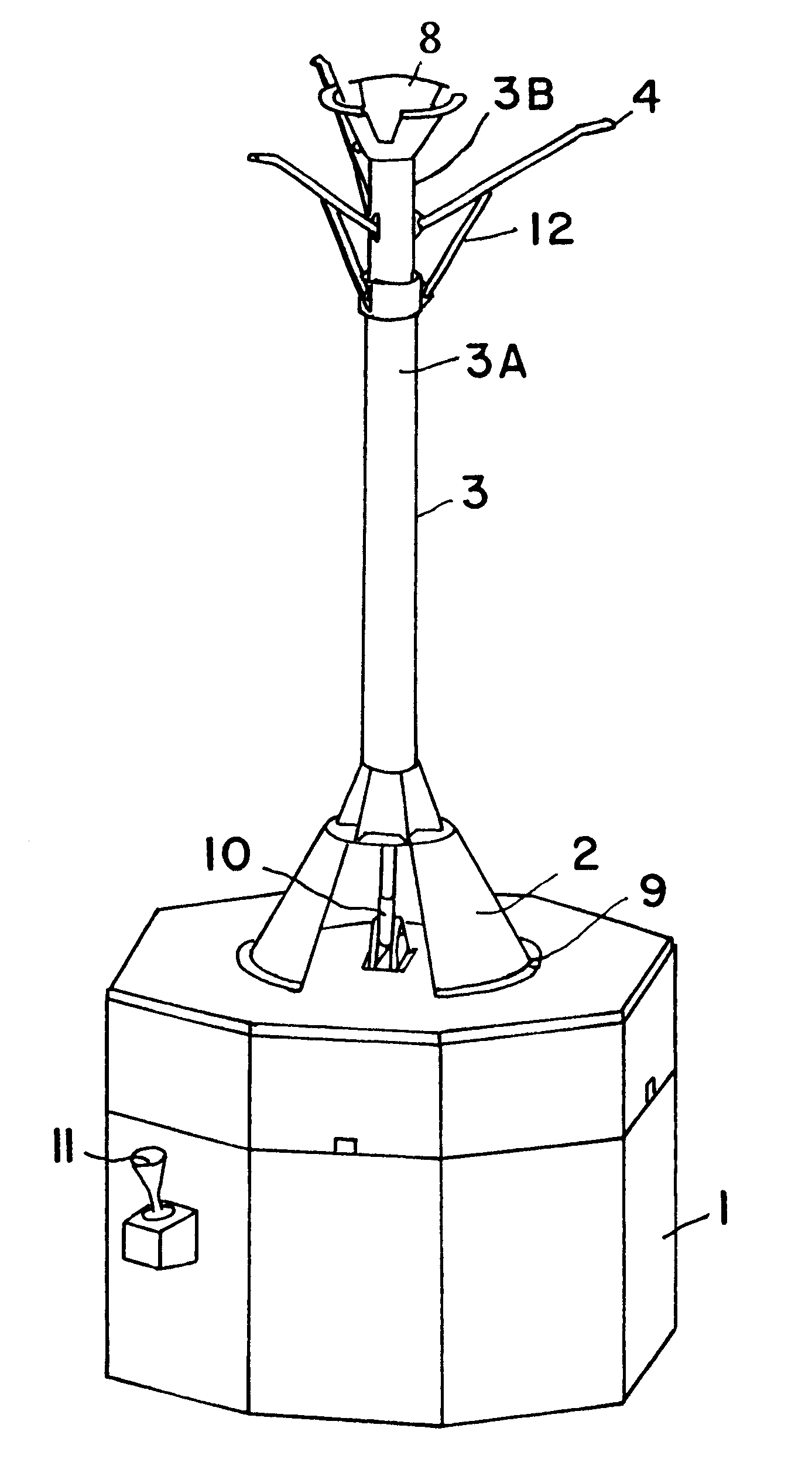
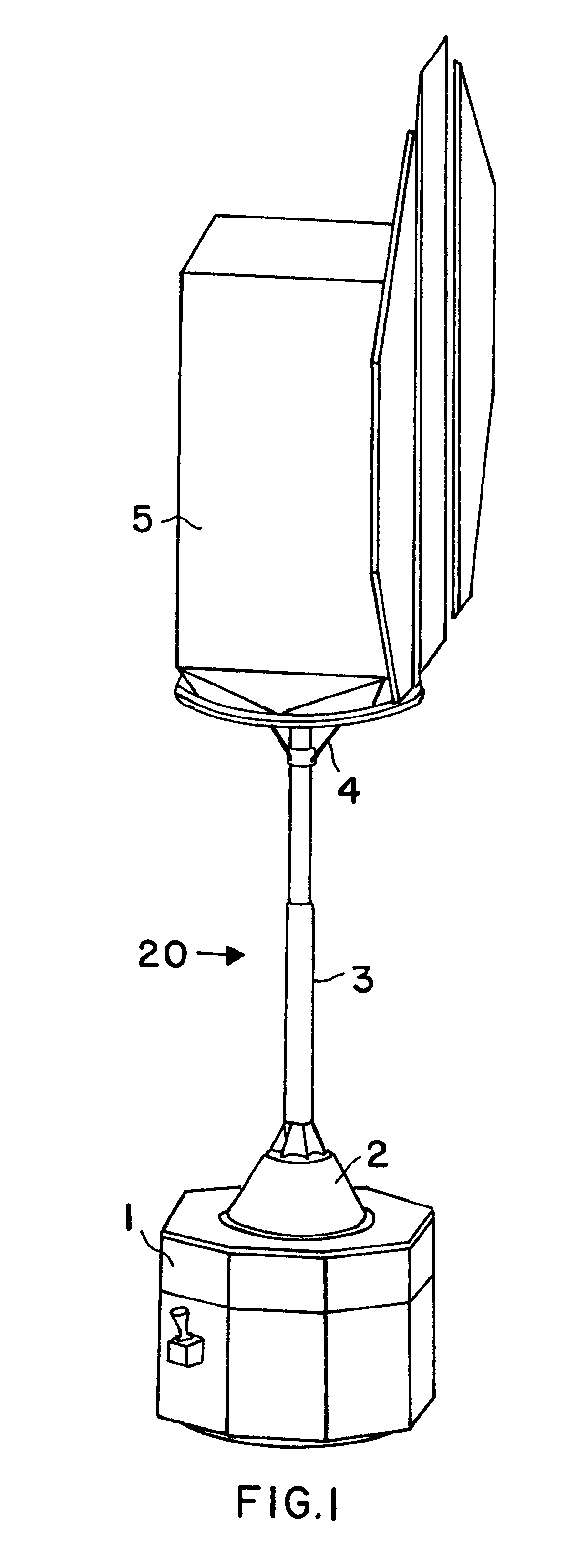
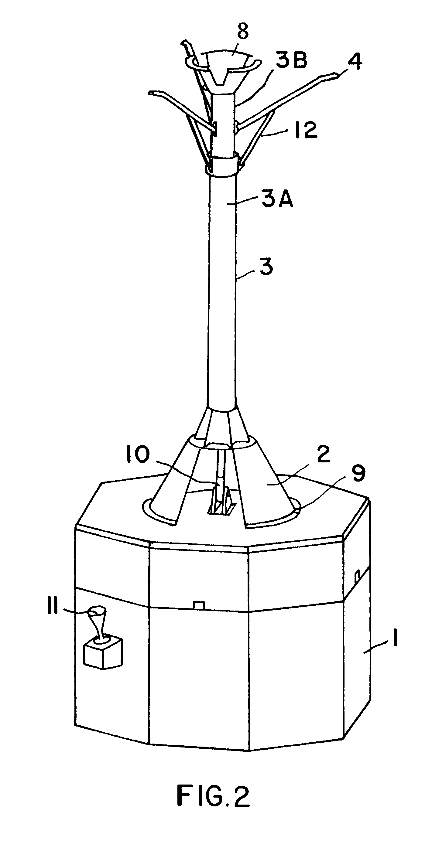
In a first embodiment, the collar 3C is fixed to the outer pipe 3A (e.g. forms a part of the outer pipe). In this arrangement, extending the inner pipe 3B from the outer pipe 3A in a telescoping fashion (as indicated by the double-headed arrow T) will move the pivot joints 4A further away from the collar 3C with the pivot joints 12A, whereby the pivot linkage formed by the pivot struts 12 causes the spreader arms 4 to spread radially outwardly away from the axis of the holder element 3. On the other hand, telescopingly sliding the inner pipe 3B into the outer pipe 3A will have the effect of pivoting the spreader arms 4 radially inwardly toward the axis of the holder element 3 and pointing substantially axially along the axis of the holder element 3 away from the recovery craft 1.

second embodiment

In effecting the radial spreading deployment of the spreader arms 4, the collar 3C is axially slidable along the inner pipe 3B and / or the outer pipe 3A, or in general along the holder element 3. Thereby, an axial sliding displacement of the collar 3C toward the recovery craft 1 will cause a radial outward spreading of the spreader arms 4, while an axial sliding of the collar 3C away from the recovery craft 1 will cause a radial inward pivoting of the spreader arms 4 closer to the axis of the holder element 3. With such a slidable collar 3C, the radial spreading deployment of the spreader arms 4 can be independent of the telescoping adjustment of the pipes 3B and 3A of the holder element 3 (or the telescoping embodiment can be omitted in an alternative embodiment). The collar 3C may be controlled and driven in a sliding manner using any conventionally known actuator means.

The adjustable spreading deployment of the spreader arms 4 is appropriately controlled to selectively bring the s...


PUM


Abstract

A recovery craft with a coupling arrangement captures, engages, and transports a defective or expended non-maneuverable spacecraft. The coupling arrangement includes a coupling mast (e.g. a telescoping pipe), a releasable rigid mount that secures one end of the coupling mast to the recovery craft, and spreader arms that are radially spreadable from the other end of the coupling mast. The spreader arms are initially radially inwardly retracted, and are inserted into an interface ring of the spacecraft. Then the spreader arms are radially outwardly extended to engage behind a protruding rim of the interface ring. A spring braces against the spacecraft. Next, the rigid mount is released and the coupling mast remains connected to the recovery craft only by a tension-transmitting cable. Thrusters of the recovery craft are activated to tow the spacecraft to a new target position, orbit, or trajectory.

Description

PRIORITY CLAIMThis application is based on and claims the priority under 35 U.S.C. .sctn.119 of German Patent Applications 100 47 518.3, filed on Sep. 22, 2000 and 100 59 914.1, filed on Dec. 1, 2000, the entire disclosures of which are incorporated herein by reference.The invention relates to an arrangement for capturing and recovering spacecraft, as well as transporting the recovered spacecraft in orbit, returning the spacecraft to earth, or leading the spacecraft into a targeted destruction through re-entry and burning-up in the earth's atmosphere, by means of a powered recovery craft, preferably in the form of a satellite equipped with a coupling mechanism between the recovery craft and the spacecraft to be recovered.BACKGROUND INFORMATIONThere are several situations in which it becomes necessary or desirable to recover, capture and transport a defective or expended satellite. For example, it may be necessary or desired to move the spacecraft to a different orbit or trajectory, ...

Claims


Application Information

Patent Timeline
Patent Type & Authority Patents(United States)
IPC IPC(8): B64G1/64B64G1/10B64G1/00B64G4/00
CPCB64G1/1078B64G4/00B64G1/646B64G1/641
Inventor STEINSIEK, FRANKGUENTHER, HANSJUERGENBISCHOF, BERND
Owner AIRBUS DEFENCE & SPACE
Why Eureka
Try Eureka