Morphing decompression in a graphics system

a graphics system and morphing technology, applied in the field of computer graphics, can solve the problems of increasing the complexity of the image displayed, the complexity of the image, and the increase in the amount of data being sent to the display device,

a graphics system and morphing technology, applied in the field of computer graphics, can solve the problems of increasing the complexity of the image displayed, the complexity of the image, and the increase in the amount of data being sent to the display device,

US6525725B1Inactive Publication Date: 2003-02-25ORACLE INT CORP

Image

  • Morphing decompression in a graphics system
  • Morphing decompression in a graphics system
  • Morphing decompression in a graphics system

Examples


Embodiment Construction

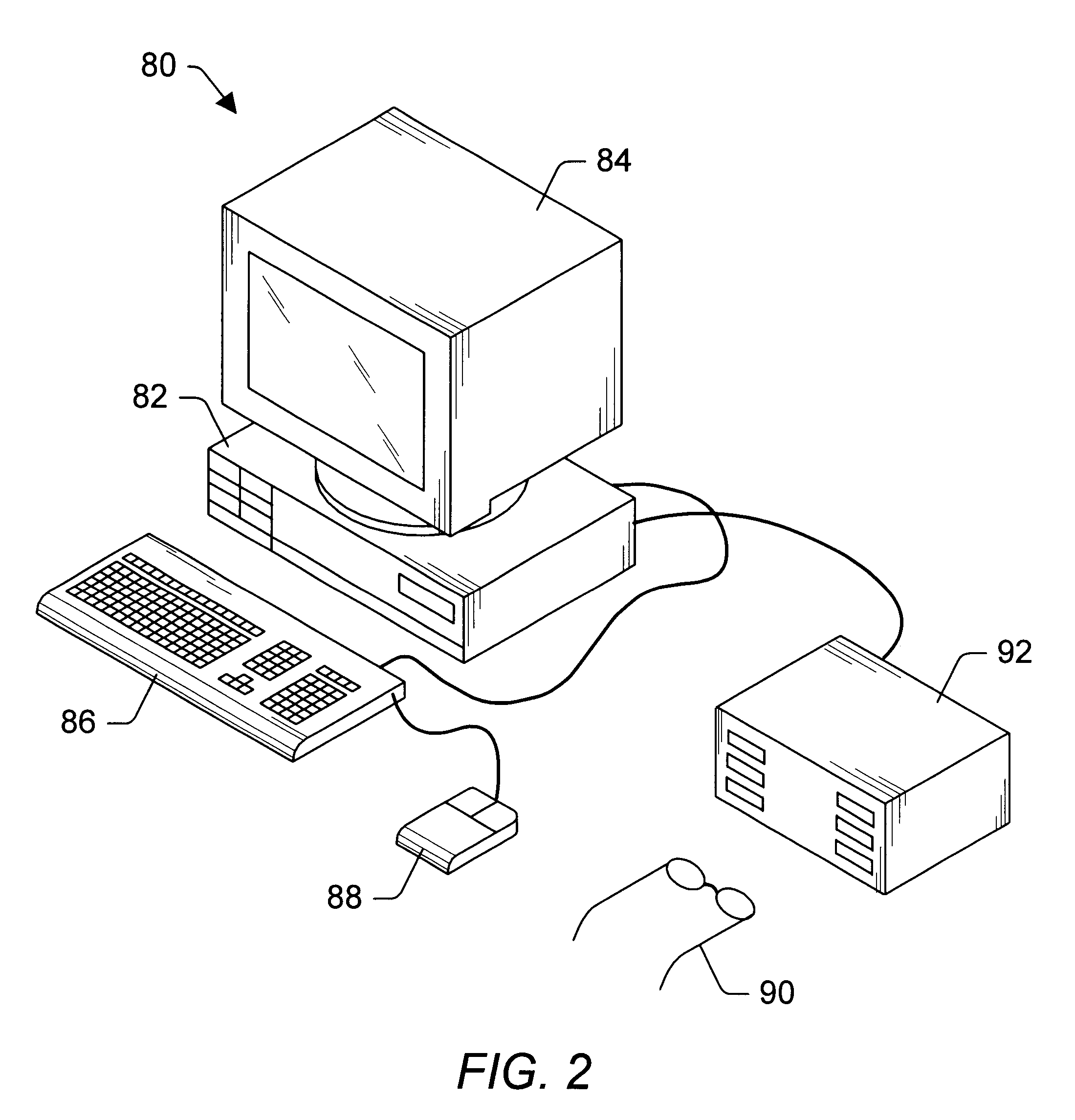
FIG. 2--Computer System

Referring now to FIG. 2, one embodiment of a computer system 80 that includes a three-dimensional (3D) graphics system is shown. Computer system 80 comprises a system unit 82 and a display device 84 coupled to the system unit 82. Display device 84 may be any of various types of display monitors or devices, e.g., a CRT, LCD, DLP, gas-plasma, projection or other type of display. Various input devices may be connected to the computer system, including a keyboard 86 and / or a mouse 88, or other input device (e.g., a trackball, digitizer, tablet, six-degree of freedom input device, head tracker, eye tracker, data glove, body sensors, etc.). Application software may be executed by the computer system 80 to display 3D graphical objects on display device 84. As described further below, the 3D graphics system in computer system 80 includes a super-sampled sample buffer with a programmable real-time sample-to-pixel calculation unit to improve the quality and realism of i...


PUM


Abstract

A method and graphics system configured to perform real-time morphing of three-dimensional (3D) objects that have been compressed into one or more streams of 3D graphics data using geometry compression techniques. In one embodiment, the graphics system has one or more decompression units, each configured to receive and decompress the graphics data. The decompression units are configured to convey the decompressed data corresponding to the morphs to a graphics processor that is configured to apply weighting factors to the graphics data. The weighted results are combined to yield a morphed object that is rendered to generate one or more frames of a morphing sequence. The weighting factors may be adjusted and reapplied to yield additional frames for the morphing sequence. A method for encoding 3D graphics data to allow morphing decompression is also disclosed.

Description

1. Field of the InventionThis invention relates generally to the field of computer graphics and, more particularly, to graphics systems that render images based on three-dimensional graphics data.2. Description of the Related ArtA computer system typically relies upon its graphics system for producing visual output on a computer screen or display device. Early graphics systems were only responsible for taking what the processor produced as output and displaying it on the screen. In essence, they acted as simple translators or interfaces. Modem graphics systems, however, incorporate graphics processors with a great deal of processing power. These new graphics systems act more like coprocessors rather than simple translators. This change is due to the recent increase in both the complexity and the amount of data being sent to the display device. For example, modern computer displays have many more pixels, greater color depth, and are able to display images with higher refresh rates th...

Claims


Application Information

Patent Timeline
25 Feb 2003
Publication
US6525725B1
IPC
G06T3/00; G06T13/00
CPC
G06T3/0093; G06T3/18
Inventors
DEERING, MICHAEL F.