Magnetically driven axial-flow pump

a technology of axial flow and axial drive, which is applied in the direction of piston pumps, positive displacement liquid engines, prosthesis, etc., can solve the problems of increasing the necessary man-hours, difficult to mechanize the assembling work, and complex assembly work of stator/rotor assemblies

Inactive Publication Date: 2003-03-04
NIPRO CORP
View PDF10 Cites 254 Cited by
  • Summary
  • Abstract
  • Description
  • Claims
  • Application Information

AI Technical Summary

Problems solved by technology

(1) The shell-shaped stator 142a and the vanes 142b have to be made separately and then combined to become the impeller 142. Besides, the vanes 142b have also to be fixed to the inner surface of the cylindrical rotor 144. The assembling work of the stator / rotor assembly is very complex. Although the individual parts can be machined with NC lathes, it is almost impossible to mechanize the assembling work.
(2) In case that the pump is to be used as a blood pump, any gaps have to be sealed, however small they may be. Accordingly, the joints between the stator 142a and the vanes 142b and those between the rotor 144 and the vanes 142b have to be coated somehow, which increases the necessary man-hours. Moreover, because one cannot look at the inside of the stator / rotor assembly once it is assembled, it is impossible to inspect visually the coating condition inside it. Thus, the pump is not reliable enough as a blood pump.
(3) The contact area between the shell-shaped stator 142a and the fluid is relatively large. Accordingly, if the pump is used as a blood pump, it is likely to destroy blood tissues and hence not suitable as a blood pump.
Besides, because the occurrence of gaps in the otherwise-inevitable joint between the rotor and the vane is precluded, it is unnecessary to coat such a joint to fill such gaps.

Method used


Image

  • Magnetically driven axial-flow pump
  • Magnetically driven axial-flow pump
  • Magnetically driven axial-flow pump

Examples


Embodiment Construction

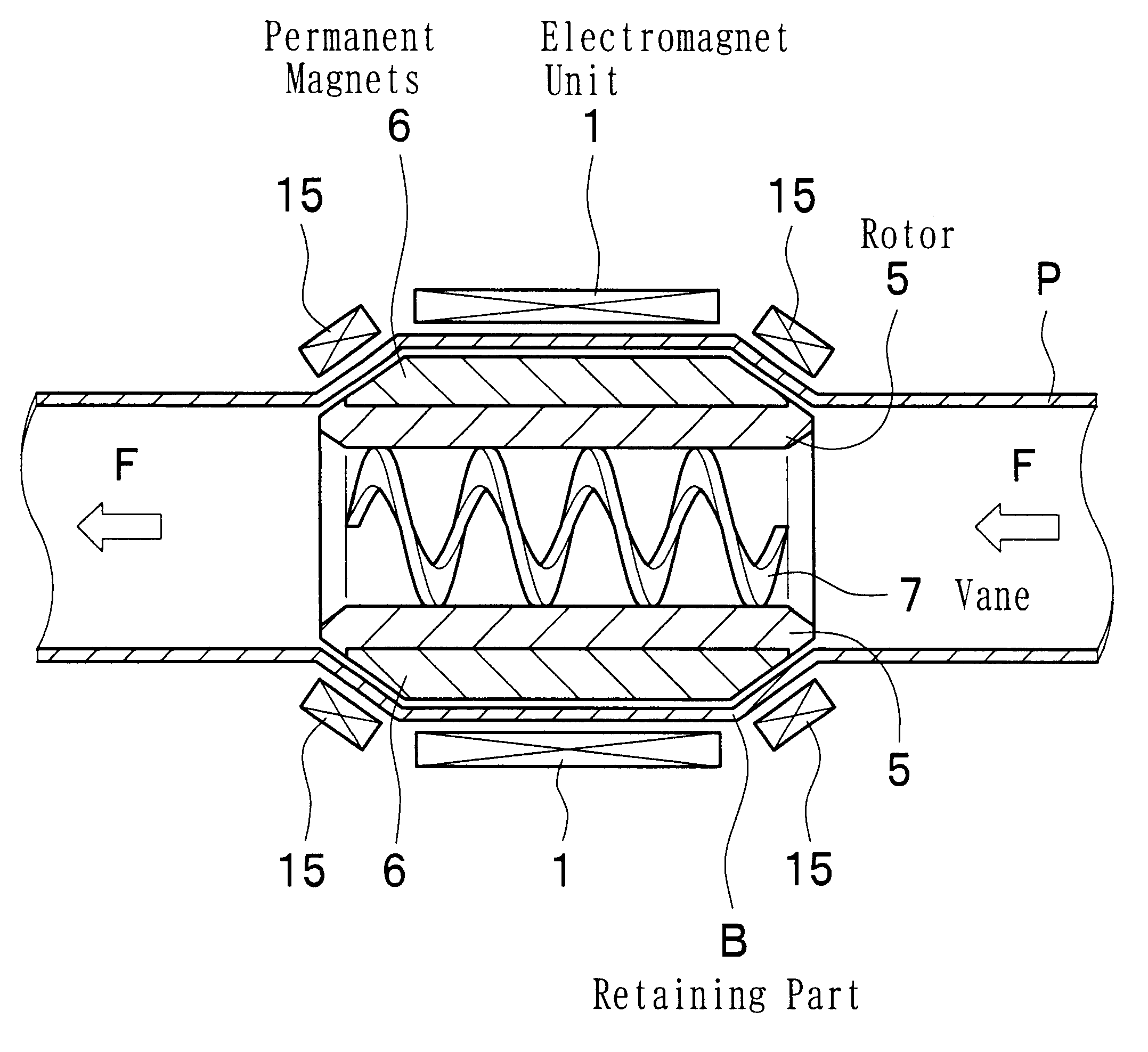
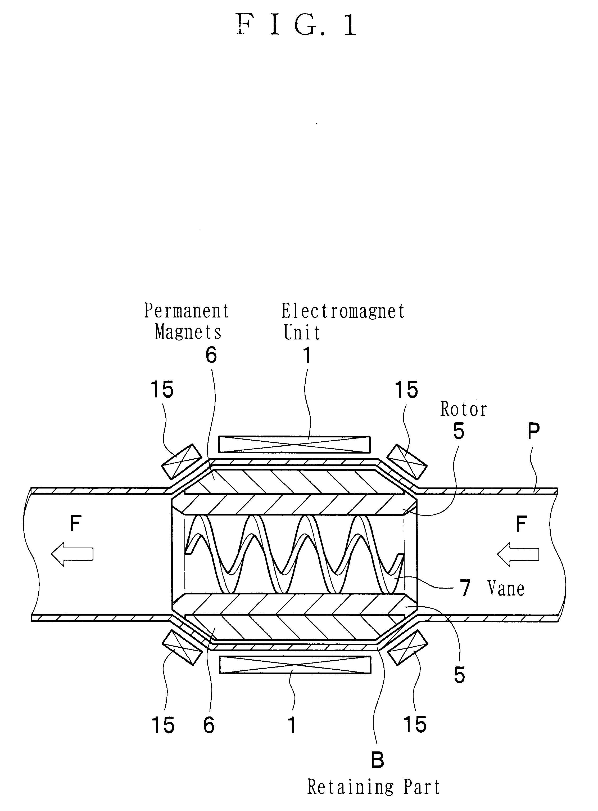
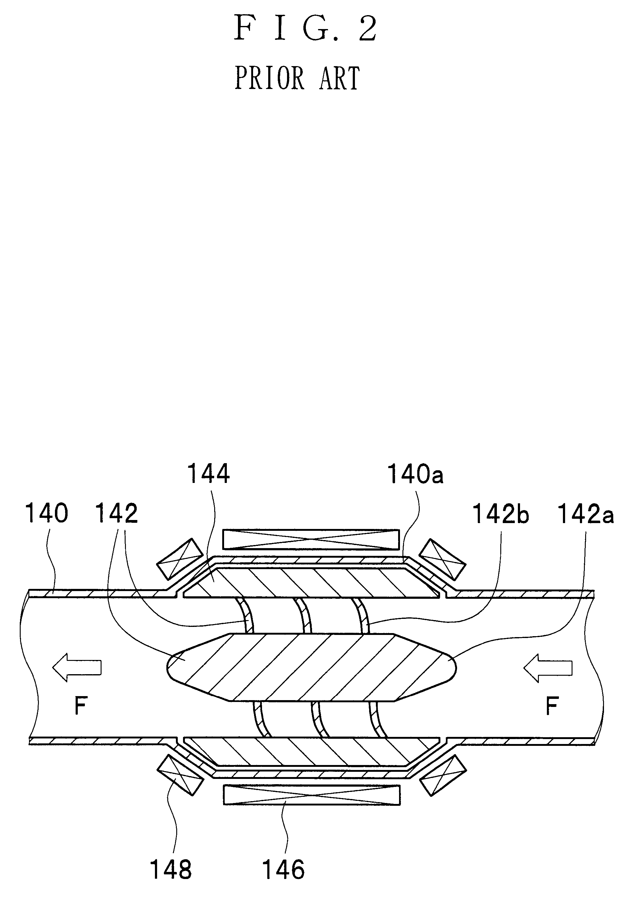
Referring to the drawings, an embodiment of magnetically driven axial-flow pump of the present invention will now be described.

In FIG. 1, blood flows in a pipe "P". The pipe "P" has a retaining part "B" which is expanded in diameter and holds the magnetically driven axial-flow pump.

The magnetically driven axial-flow pump consists basically of an electromagnet unit 1, a rotor 5, permanent magnets 6, and a vane 7.

The rotor 5 is disposed in the retaining part "B" so as to be freely rotatable. The rotor 5 is made of a grindable material such as iron or ceramic. The rotor 5 made of iron or ceramic is hard, strong, and durable.

The rotor 5 is in the shape of a cylinder and its wall tapers off at each end so as to make its inner diameter enlarge toward said end.

The spiral vane 7 is formed on the inner surface of the rotor 5. The central portion along the axis of the vane 7 is hollow. Therefore, the rotor 5 and the vane 7 can be made in one piece with an NC machine by, for example, the follo...


PUM


Abstract

A magnetically driven, axial flow pump comprises an electromagnetic unit arranged about the periphery of a pipe. A cylindrical rotor is accommodated within the pipe and is equipped with permanent magnets mounted on the periphery. A spiral, hollow vane is formed on an inner surface of the rotor by either casting or by cutting, such as with a NC machine, thus precluding the occurrence of gaps between the rotor and the vane. The lack of gaps within the pump makes the pump suitable for use as a blood pump.

Description

BACKGROUND OF INVENTIONThe present invention relates to a magnetically driven axial-flow pump. More specifically, this invention relates to a pump of which the vane is magnetically driven and which is built in a pipe to feed the fluid in it.The magnetically driven axial-flow pump of the present invention can be used for any purposes in any technical fields as far as it is supposed to impel the fluid in a pipe. The pump can be used as medical blood pumps, industrial fluid pumps, and engines for movement such as marine motors.The Japanese Unexamined Patent Publication No. 71492 / H5 (1993) disclosed a magnetically driven axial-flow pump.Referring to FIG. 2, the pump of the prior art will be described. A cylindrical rotor 144 is disposed in an expanded part 140a of a pipe 140 so as to be rotatable freely. An impeller 142 is fixed inside the cylindrical rotor 144. The impeller 142 consists of a shell-shaped stator 142a and vanes 142b, the latter fixed radially to the former. The vanes 142...

Claims


Application Information

Patent Timeline
Patent Type & Authority Patents(United States)
IPC IPC(8): F04D13/06F04D3/02F04D3/00F04D13/02A61M1/10H02K7/14
CPCF04D3/02F04D13/0646A61M1/101H02K7/14Y10S415/90A61M1/1015A61M60/422A61M60/148A61M60/237A61M60/10A61M60/806
Inventor NODA, HIROYUKI
Owner NIPRO CORP
Why Eureka
Try Eureka