Transponder apparatus

a transponder and apparatus technology, applied in the field of transponder apparatus, can solve the problems of complex repeater systems that are prone to interference, repeater systems that lack the ability to provide adequate isolation between input and output, and the repeater system is also more complex, so as to reduce the vulnerability of interference, eliminate clock jitter, and provide sufficient power

Inactive Publication Date: 2003-03-04
ITT DEFENSE & ELECTRONICS
View PDF7 Cites 0 Cited by
  • Summary
  • Abstract
  • Description
  • Claims
  • Application Information

AI Technical Summary

Benefits of technology

More specifically, it is an object of the present invention to provide a transponder that minimizes its vulnerability to interference.
It is another object of this invention to provide a transponder that is able to provide sufficient power at low input levels.
It is an object of the present invention to eliminate clock-jitter from a re-transmitted signal. In other words, the present invention allows for an accurate and consistent reproduction of the leading edge of the return signal, thereby allowing for the elimination of interference caused by random and / or improperly generated return signals.
The transponder of the present invention provides important advantages over the prior art devices. Most importantly, it allows for the accurate and consistent reproduction of the leading edge of the return signal, thereby allowing for the elimination of interference caused by random and / or improperly generated return signals that can be improperly construed by the radar system as the return pulse of the transponder.

Problems solved by technology

As radar systems become more sophisticated, and more sensitive, repeater systems have also become more complex.
However, these complex repeater systems are prone to interference, stemming, in part, from feedback of the retransmitted signal generated by the repeater.
Further, these repeater systems lack the ability to provide adequate isolation between input and output to provide sufficient power at low input signal levels.
Notwithstanding the foregoing use of repeater and transponder systems, as stated such prior art systems are prone to interference and lack the ability to provide adequate isolation between input and output to produce sufficient power at low input signal levels.
Furthermore, prior art radar transponders add unacceptable clock jitter to the retransmitted signal for certain applications.
Still further, the retransmitted signal from the transponder is additionally subject to interference resulting from the feedback.

Method used


Image

  • Transponder apparatus
  • Transponder apparatus
  • Transponder apparatus

Examples


Embodiment Construction

In the following description, for the purposes of explanation, numerous specific details are set forth in order to provide a more thorough understanding of the present invention. It will be apparent, however, to one skilled in the art, that variations of the embodiments disclosed herein are also possible.

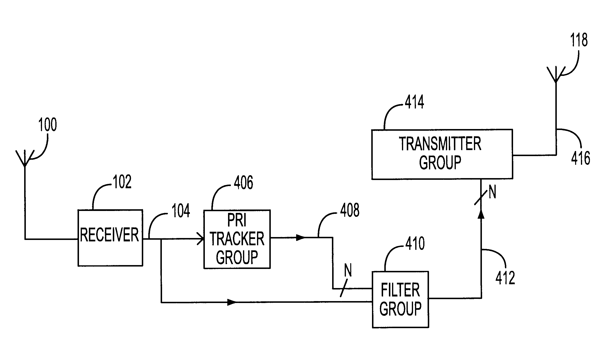
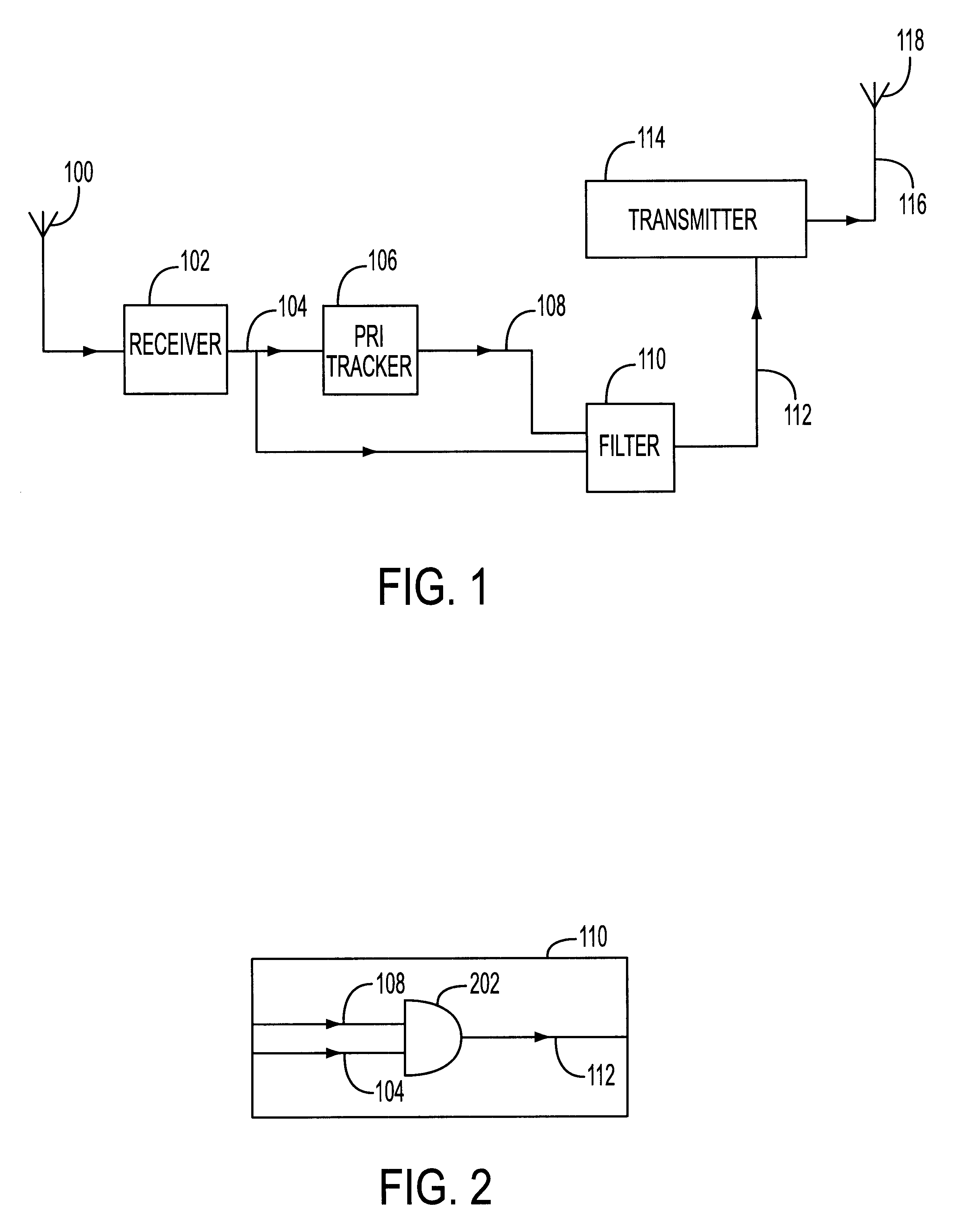
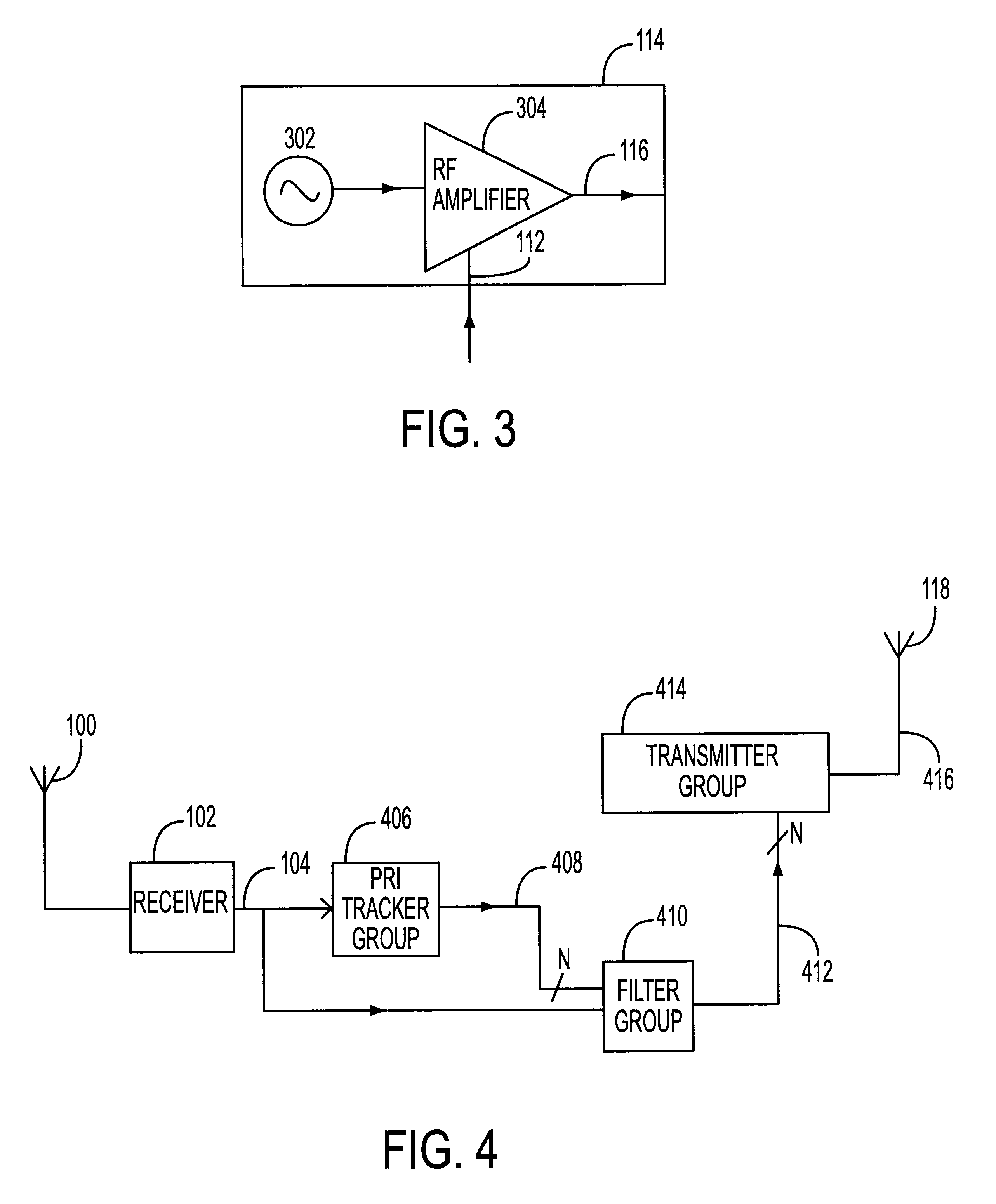
FIG. 1 depicts an exemplary embodiment of a triggered transponder in accordance with the present invention. As illustrated in FIG. 1, pulsed RF signals received by receiving antenna 100, are sent to receiver 102. Although receiver 102 may be a dedicated receiver, designed to receive a specific frequency or specifically modulated signal, in accordance with the present invention, receiver 102 may be a tunable receiver, designed to controllably receive a plurality of frequencies or types of modulated signals. The received signal 104 that is output from receiver 102 is sent to both a PRI tracker 106 and a filter 110. In one embodiment, the receiver 102 functions to demodulate the incomi...


PUM


Abstract

A method and apparatus for transponding pulsed RF signals is provided. The method comprises receiving, with a receiver, pulsed RF signals having a plurality of PRIs. Further the method includes generating, with a PRI tracker, control signals from the received pulsed RF signals. The method then filters the received pulsed RF signals with the control signals to thereby obtain enable signals, which in turn control a transmitter permitting retransmission without clock jitter.

Description

I. FIELD OF INVENTIONThe present invention relates generally to a transponder apparatus for receiving and re-transmitting pulsed RF signals, and more specifically, a tunable transponder apparatus that provides for the retransmission of a received signal, while minimizing interference and / or clock jitter associated with prior art transponders.II. BACKGROUND OF THE INVENTIONRadar identification systems have been known for many years, having originated during the Second World War. In such systems, an interrogation apparatus sends out a radio frequency pulse, which is recognized by an identification apparatus fitted to a vehicle or other object within range of the interrogation apparatus.Upon receipt of the pulse, a repeater sends back a reply signal, generally in the form of a train of pulses, which is processed and displayed at a receiving station. Such systems, which require the provision of a responder on the vehicle or other object, are known as secondary radars, or repeaters, as d...

Claims


Application Information

Patent Timeline
Patent Type & Authority Patents(United States)
IPC IPC(8): G01S13/76G01S13/00G01S7/02G01S13/78
CPCG01S7/021G01S13/765G01S13/781
Inventor MORCHEL, HERMAN G.TEDESCO, ANGELO R.CURTIS, CHARLES M.
Owner ITT DEFENSE & ELECTRONICS
Why Eureka
Try Eureka