High precision vibration damping system

a vibration damping and high-precision technology, applied in the field of very long-range optical instruments, can solve the problems of low-level transient shock, persistent vibration, and perturb the optics of instruments, and achieve the effect of dampening vibrations

Inactive Publication Date: 2003-03-18
FOSTER-MILLER
View PDF17 Cites 5 Cited by
  • Summary
  • Abstract
  • Description
  • Claims
  • Application Information

AI Technical Summary

Benefits of technology

It is therefore an object of this invention to provide a system which effectively dampens vibrations.

Problems solved by technology

These shape changes can induce low level transient shocks and persistent vibrations that perturb the instrument's optics and reduce or destroy the quality of the scientific observation.
These vibrations cause the departure of structures and mechanisms from ideal linear behavior with very small, often nanometer level, deformations.
While these systems can be very effective in damping low level vibrations, they tend to be very massive, complex and expensive to develop and operate.
Furthermore, they require valuable spacecraft power to operate and, due to their increased complexity, are not extremely reliable or stable.
While these systems are less complex and less expensive than active systems, they cannot currently provide the high performance of active systems; they cannot be reconfigured once the spacecraft is launched; and the performance of material or fluid based passive systems are very sensitive to the ambient temperature.
While friction in space structure joints has long been recognized as a dominant source of dissipation in precision structures, it has not been used as an intentional passive source of vibration damping.
The three main reasons for this are: 1) it is difficult to predict and control the levels of damping due to friction in structural joints; 2) loss factors due to friction are generally limited to 1-5%; and 3) any dissipation due to friction can be accompanied by large nonlinearities in the structural dynamics, making the active control of the structure more difficult.

Method used


Image

  • High precision vibration damping system
  • High precision vibration damping system
  • High precision vibration damping system

Examples


Embodiment Construction

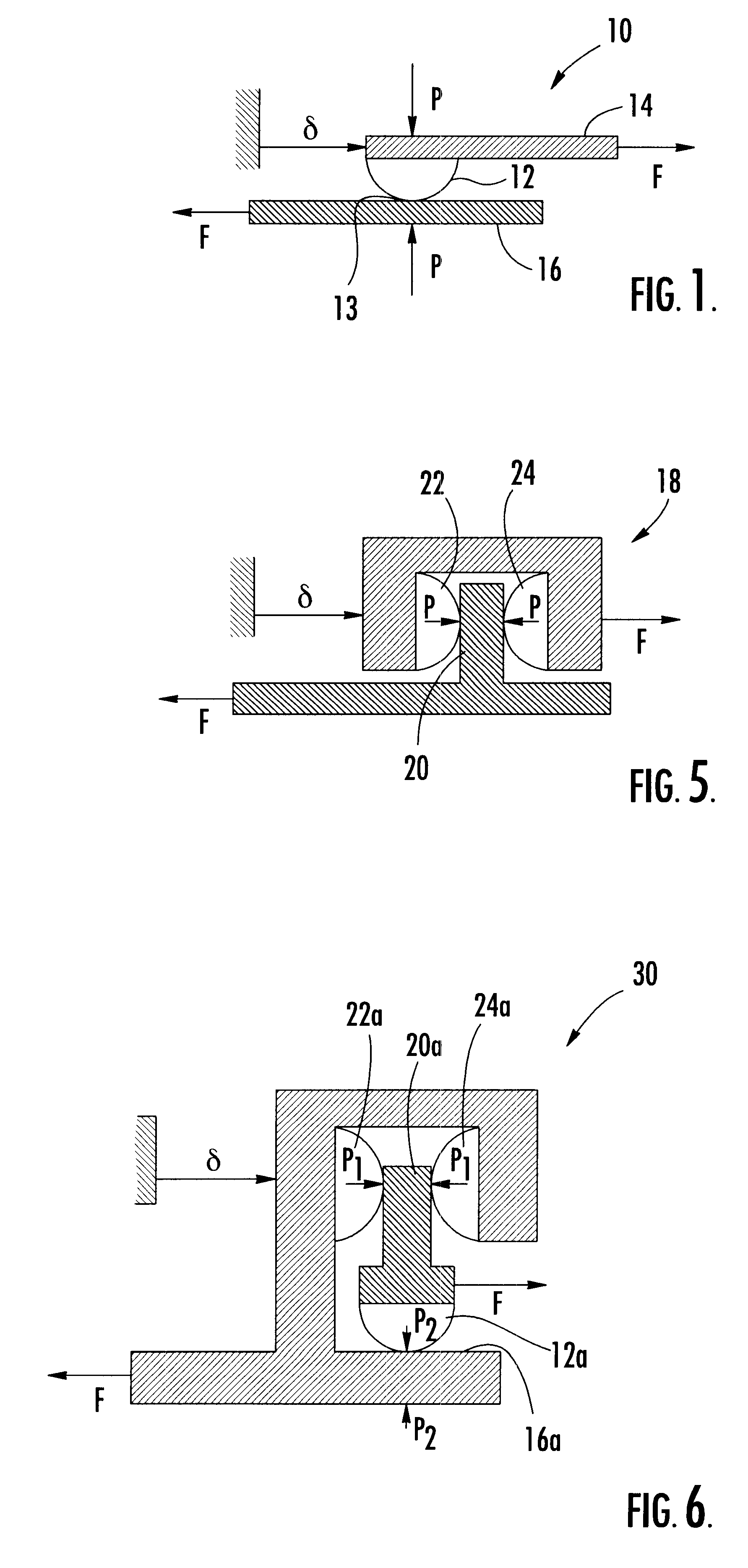
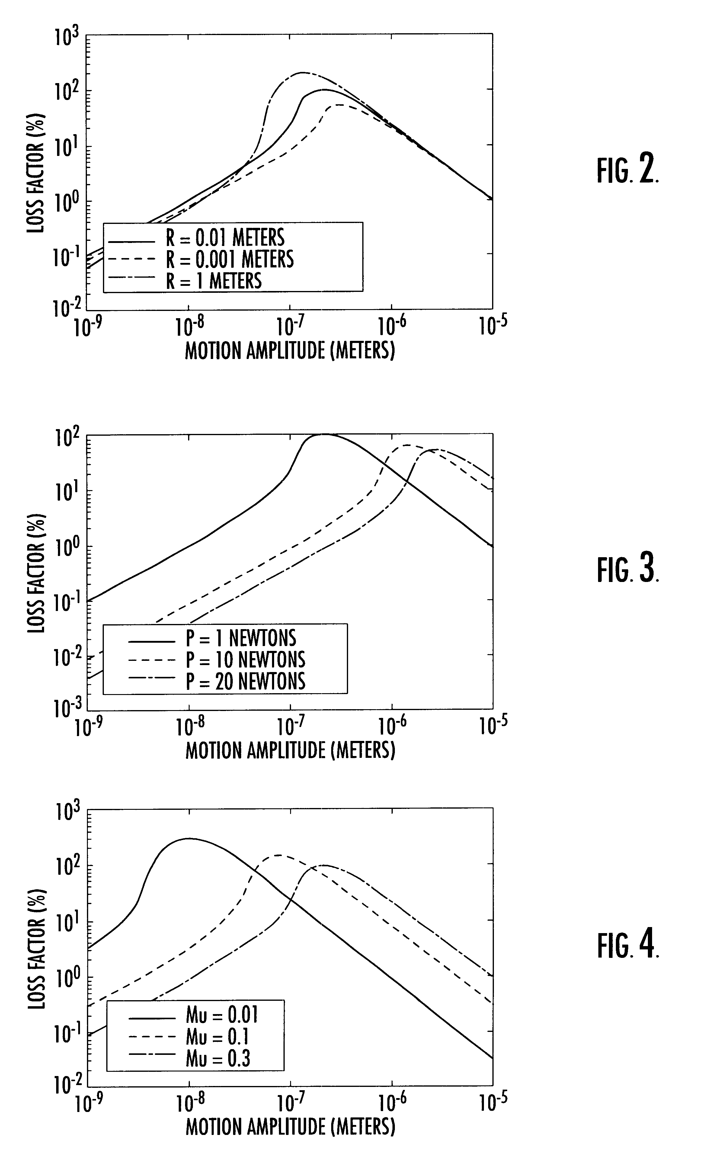
Referring now to FIGS. 1-3, the underlying physics which define the operation of the present invention will be described. FIG. 1 is a schematic diagram of a sliding sphere element 10. Sliding sphere element 10 includes a spherical element 12 mounted to a beam 14, the spherical element 12 being biased against the bearing surface 13 of plane 16 by a pressure P and being slideable along plane 16. Throughout the specification, the elements and contacts that are described as being spherical are not necessarily entire spheres, and preferably comprise only a segment of a sphere.

When the spherical element 12 is slid from an initial state in which there is no shear stress, the entire contact patch of the spherical element 12 is motionless relative to the plane 16. Sliding begins at the edges of the contact patch and, as the spherical element 12 is slid, the area of sliding contact grows inwardly in a circular annulus. When the sphere is stopped and the motion is reversed compliance of the sp...


PUM


Abstract

A damping system is disclosed which includes a housing that receives vibrations, a mounting platform movably disposed with respect to the housing, at least one bearing surface on or attached to one of the housing and the platform, and at least one frictional member on or attached to the other of the housing and the platform in contact with the bearing surface. The system frictionally dampens vibrations received by the housing and isolates the platform from vibrations.

Description

This invention relates generally to a damping system, and more particularly to a system for reducing vibrations at very low levels of motion.BACKGROUND OF INVENTIONIn the field of very-long-range optical instruments, particularly in the case of optical instruments used on spacecraft, it is essential to reduce vibrations which can interfere with the operation of the optical instrument, since the performance of such instruments depends on maintaining the precision and stability of the instruments to within nanometers of the ideal shape of the instrument. Friction and freedom in the joints of deployed structures have the capacity to change the shape of the instrument at the micron and nanometer levels of resolution. These shape changes can induce low level transient shocks and persistent vibrations that perturb the instrument's optics and reduce or destroy the quality of the scientific observation. These vibrations cause the departure of structures and mechanisms from ideal linear beha...

Claims


Application Information

Patent Timeline
Patent Type & Authority Patents(United States)
IPC IPC(8): F16F7/02F16F7/00F16F15/00
CPCF16F7/02
Inventor WARREN, PETER A.PETERSON, LEE D.HINKLE, JASON D.
Owner FOSTER-MILLER
Why Eureka
Try Eureka