Wireless communication transceiver having a dual mode of operation

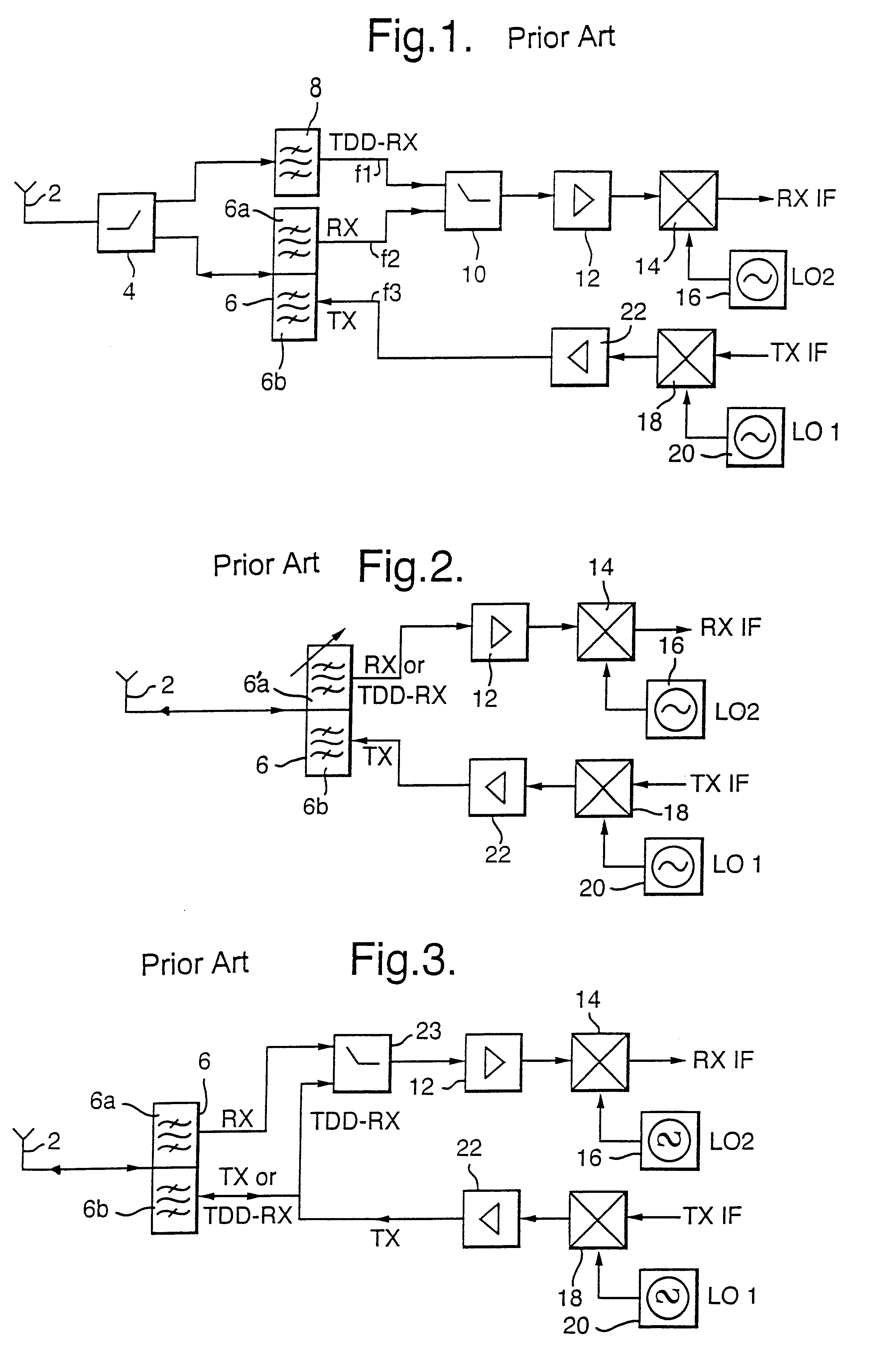
a wireless communication and transceiver technology, applied in the field of cell telecommunication networks, can solve the problems of loss or garble of information carried by the signal which should be received, transmission of a much greater strength than the received signal, and two switches 4 and 10 both need to have good isolation

Inactive Publication Date: 2003-03-18
NOKIA TECHNOLOGLES OY
View PDF24 Cites 99 Cited by
  • Summary
  • Abstract
  • Description
  • Claims
  • Application Information

AI Technical Summary

Problems solved by technology

This transceiver has the disadvantage that the two switches 4 and 10 both need to have good isolation.
The information carried by the signal which should be received may therefore be lost or garbled.
This problem is compounded by the fact that the transmitted signal will have a much greater strength than the received signal.
Radio frequency switches having the required isolation to deal with this problem are both expensive and difficult to implement in practice.
Another problem associated with the transceiver shown in FIG. 1 is that the first switch 4 needs to have good linearity so as to avoid distorting the signal which is to be transmitted by the antenna 2.
This further increases the costs associated with the first switch 4 as well as the difficulties associated with the implementation of that switch.
In particular, it is difficult to implement a switch which has good isolation as well as good linearity.
However, it is again difficult and expensive to implement a tunable duplex filter which has sufficient isolation to prevent at least a part of the signal to be transmitted, in the FDD mode, from reaching the low noise amplifier 12.
Isolation is an inherent problem with standard duplex filters but this problem is made worse if the duplex filter has a tunable filter portion.
The disadvantage with this arrangement is that the switch 23 has to deal with radio frequency signals and provide good isolation, typically 50 to 60 decibels.
This is a similar problem to that which occurs with the arrangement shown in FIG. 1.
It is difficult and expensive to implement a switch which has both the required linearity and the required isolation.
This is because there will be a coupling loss between the antennae which then reduces the amount of isolation required.
This coupling loss arises because the first and second antennae are physically spaced apart from one another.

Method used


Image

  • Wireless communication transceiver having a dual mode of operation
  • Wireless communication transceiver having a dual mode of operation
  • Wireless communication transceiver having a dual mode of operation

Examples


first embodiment

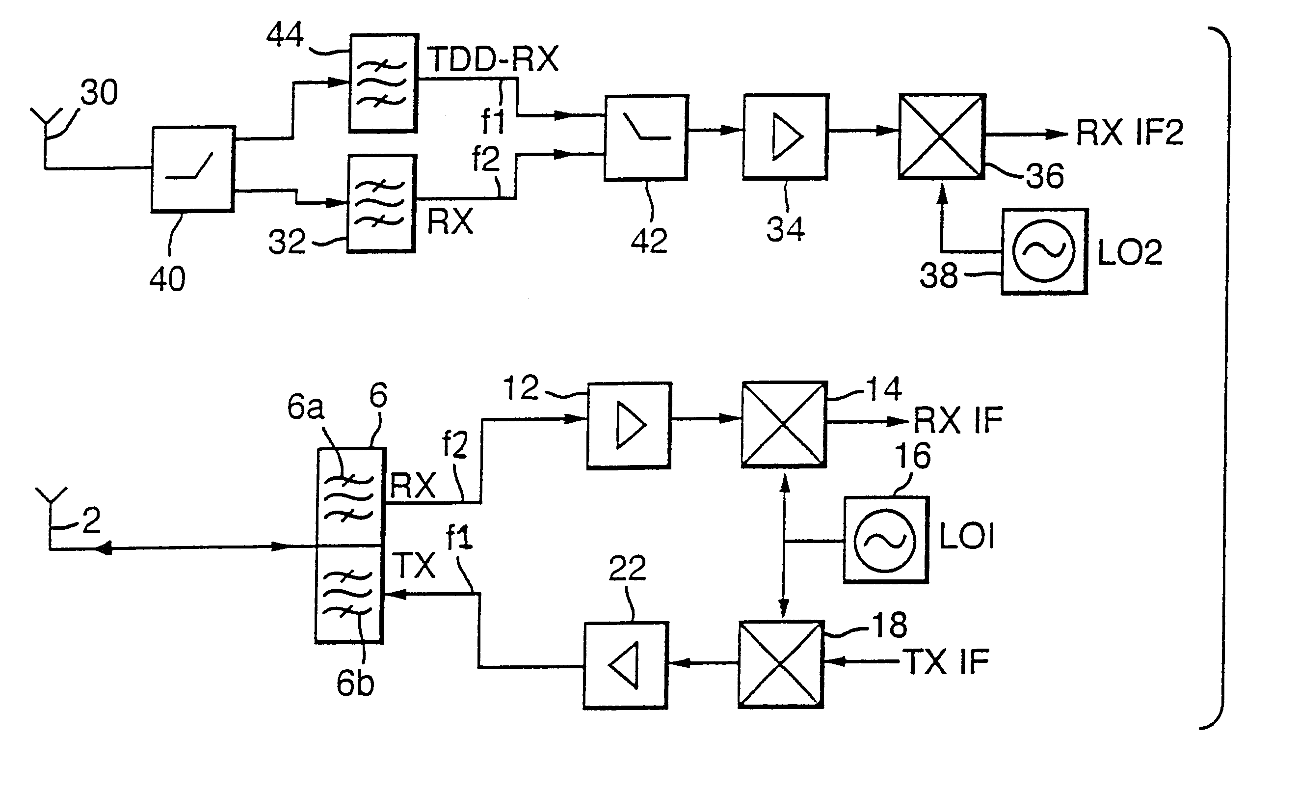
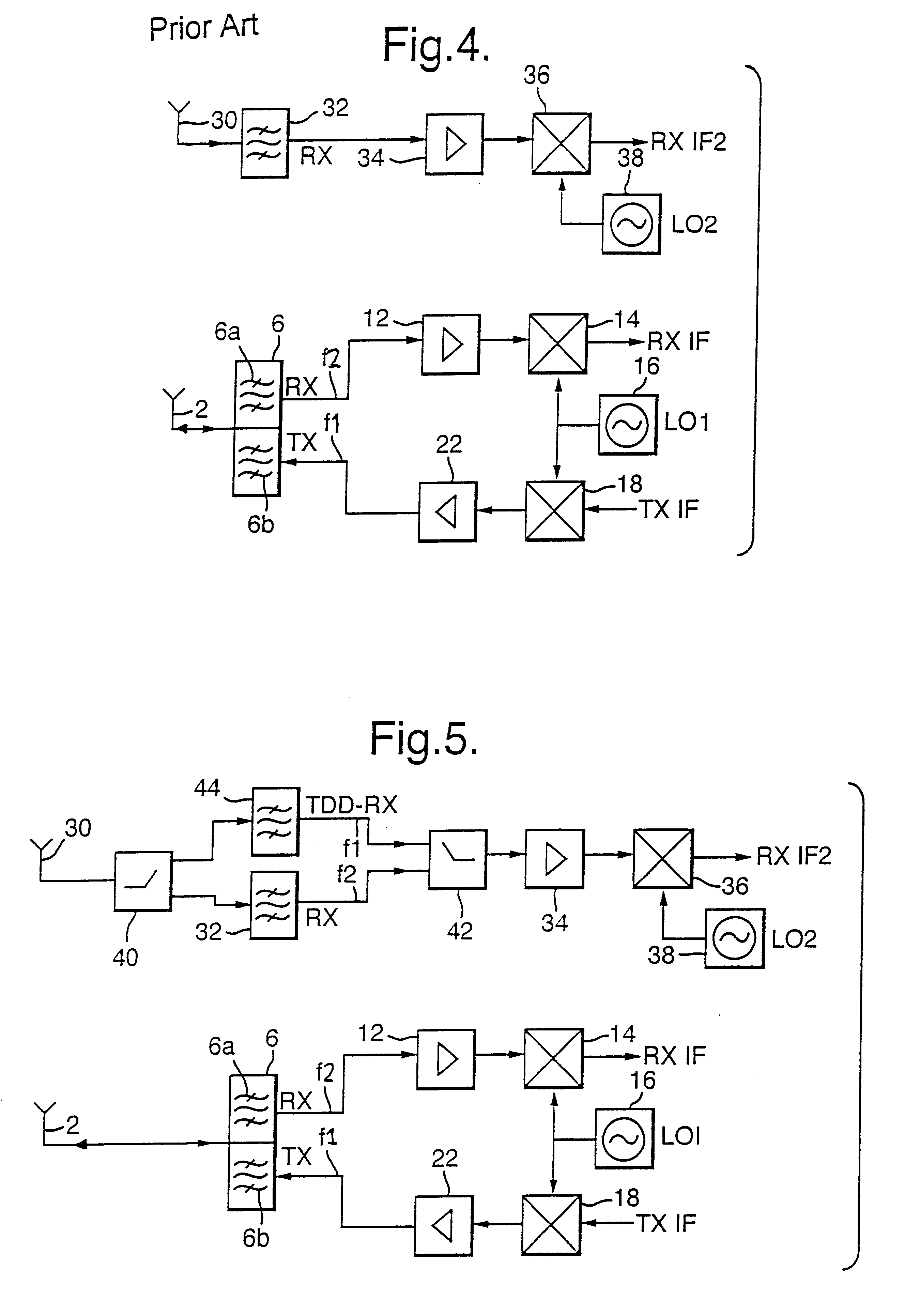
Reference will now be made to FIG. 5 which shows the present invention. It should be appreciated that those components are the same as shown in the previous Figures are referred to by the same reference numeral.

The arrangement shown in FIG. 5 has two modes of operation. Preferably the FDD mode of operation uses CDMA whilst the TDD mode of operation uses TDMA or a TDMA / CDMA hybrid mode of operation. In the FDD mode of operation, the first antenna 2 is arranged to transmit signals in the frequency range F1. It should be appreciated that signals will be sent in one of the channels within the first frequency range. The signal which is to be transmitted is input at an intermediate frequency to the second mixer 18. The second mixer 18 has an input from the first high frequency synthesizer 16 which generates a signal at a given frequency. The output of the second mixer 18 represents the signal to be transmitted at the radio frequency. The radio frequency signal is then is amplified by the ...

second embodiment

Reference will now be made to FIG. 6 which shows the present invention. The arrangement shown in FIG. 6 is the same as that shown in FIG. 5 except that the first and second switches 40 and 42 and the first and second receive filters 32 and 34 have been replaced by a tunable receiver filter 46 which can be tuned to the frequency range F1 or F2 depending on the mode of operation. In the FDD mode of operation, the tunable filter 46 will be tuned to the frequency range F2. Thus the same signal in the frequency range F2 is received via the first and second antennae 2 and 30 giving space diversity. The signals are transmitted via the first antenna 2 and are in the frequency range F1.

In the TDD mode of operation, the tunable filter 46 will be tuned to frequency F1, that is the frequency used in the FDD mode of operation for the transmitted signals. The tunable filter 46 has a control input which controls the frequency to which the filter 46 is tuned, in dependence on the mode of operation....

third embodiment

Reference will now be made to FIG. 7 which shows the present invention. Those components which are the same as shown in FIGS. 5 and 6 will not be described again and will be referenced by the same reference numerals. In this embodiment, the first frequency range F1 is divided into two parts as can be seen from FIG. 10c. In particular, the first part of the frequency range Fa is used to transmit signals from the mobile station to the base station in the FDD mode. The second part Fb of the first frequency range is used by the base station to transmit signals to the mobile station in the TDD mode of operation. Additionally this same frequency range Fb may be used by the mobile station in the TDD mode of operation to transmit signals to the base station. The base station uses the second frequency range F2 to transmit signals to the mobile station in the FDD mode of operation.

The components connected to the second antenna 30 in this embodiment are the generally the same as the components...


PUM


Abstract

A transceiver for use in wireless communications including a first antenna and first filter coupled thereto to transmit signals in a first frequency range and a second antenna and second filter means coupled thereto to receive signals in the first frequency range or a second different frequency, in dependence on a mode of operation of the transceiver. In a first mode of operation the transceiver is arranged to transmit signals in the first frequency range via the first antenna and to receive signals in the second frequency range via the second antenna, and in a second mode of operation, the transceiver is arranged to receive signals in the first frequency range via the second antenna. Alternatively, the second antenna and second filter may receive signals in a third frequency range and in the second mode of operation, the transceiver is arranged to receive signals in the third frequency range via the second antenna.

Description

The present invention relates to a transceiver for use in wireless communication. In particular, but not exclusively, the present invention relates to a transceiver that has a dual mode of operation where in the first mode of operation the signals received and the signals transmitted by the transceiver are in different frequency ranges and in the second mode of operation the received and transmitted signals are in the same frequency range.BACKGROUND TO THE INVENTIONIn most cellular telecommunication networks, mobile stations in a cell associated with a base transceiver station use a first frequency range to transmit signals to the base transceiver station. The base transceiver station uses a second, different, frequency range to transmit signals to the mobile stations in the cell associated with that base transceiver station. This is known as the frequency division duplex (FDD) mode of operation and has been used in analogue cellular telecommunication systems as well as in the curre...

Claims


Application Information

Patent Timeline
Patent Type & Authority Patents(United States)
IPC IPC(8): H03D7/00H03D7/16H04B7/12H04B1/52H04B1/50H04B7/02H04B7/08
CPCH03D7/165H04B7/12H04B1/525
Inventor VUORIO, JUHALILJA, HARRI
Owner NOKIA TECHNOLOGLES OY
Why Eureka
Try Eureka