Visual imaging system for ultrasonic probe

a technology of ultrasonic probe and visual imaging system, which is applied in the field of non-invasive ultrasonic systems, can solve the problems of difficult to recapture the prior image location, inability to suitably compare point-by-point, and different images formed at different times or from different vantage points

Inactive Publication Date: 2003-04-01
GUIDED THERAPY SYSTEMS LLC
View PDF25 Cites 241 Cited by
  • Summary
  • Abstract
  • Description
  • Claims
  • Application Information

AI Technical Summary

Benefits of technology

In accordance with another aspect of the present invention, the imaging system can comprise a positioning indicator located within the transducer which can facilitate the determination of the position and / or orientation of the transducer with respect to the patient. In addition, this positioning information can be utilized to suitably scale the ultrasonic image of the treatment region to correspond with the positional image of the patient to provide a fused image.

Problems solved by technology

As a consequence, if the patient's body shifts between taking images, or if the transducer must be repositioned after imaging, it is often difficult to recapture the prior image location.
Moreover, an additional problem associated with the aforementioned scanning techniques is that each imaging process is particular to a patient, and thus sensitive to the patient's position with respect to the imaging device.
Because of their unique or distinct features, images formed at different times, or from different vantage points, cannot be suitably compared on a point-by-point basis.
This prevents an accurate comparison of the scanning regions from one scanning session to another, and from one patient to another.
Prior art systems for aiding or guiding the positioning of medical devices are generally cumbersome and complex.
Such machinations of the probing process creates a system that is relatively cumbersome for the practitioner using a hand-held transducer.
An additional problem with existing systems is found in the difficulty with which a prior imaging plane can be recaptured for comparison purposes, a problem which becomes even more significant with the use of hand-held transducer.
A disadvantage inherent in the Allen system, however, is that the fiducial implants remain implanted in the patient between imaging session.
In addition, the Allen system does not facilitate the scanning or diagnosis of other patients, but only operates effectively for the same patient.
Generally, these techniques are complex as in the U.S. Pat. No. 5,748,767 issued to Raab, or are limited in their use, as in U.S. Pat. No. 5,230,338 issued to Allen et al.
That is, use of such techniques essentially requires the implementation of cumbersome equipment, such as an electrogoniometer and reference block, or requires that elements of the system remain with the patient between scans, such as the implants in Allen.
In that regard, such methods are inadequate for medical specialist who desire a simpler and less cumbersome manner to record a tool position or orientation which correlates with a prior image, to facilitate the return to the precise location of the prior treatment in that patient or, alternatively, a second patient undergoing similar treatment.

Method used


Image

  • Visual imaging system for ultrasonic probe
  • Visual imaging system for ultrasonic probe
  • Visual imaging system for ultrasonic probe

Examples


Embodiment Construction

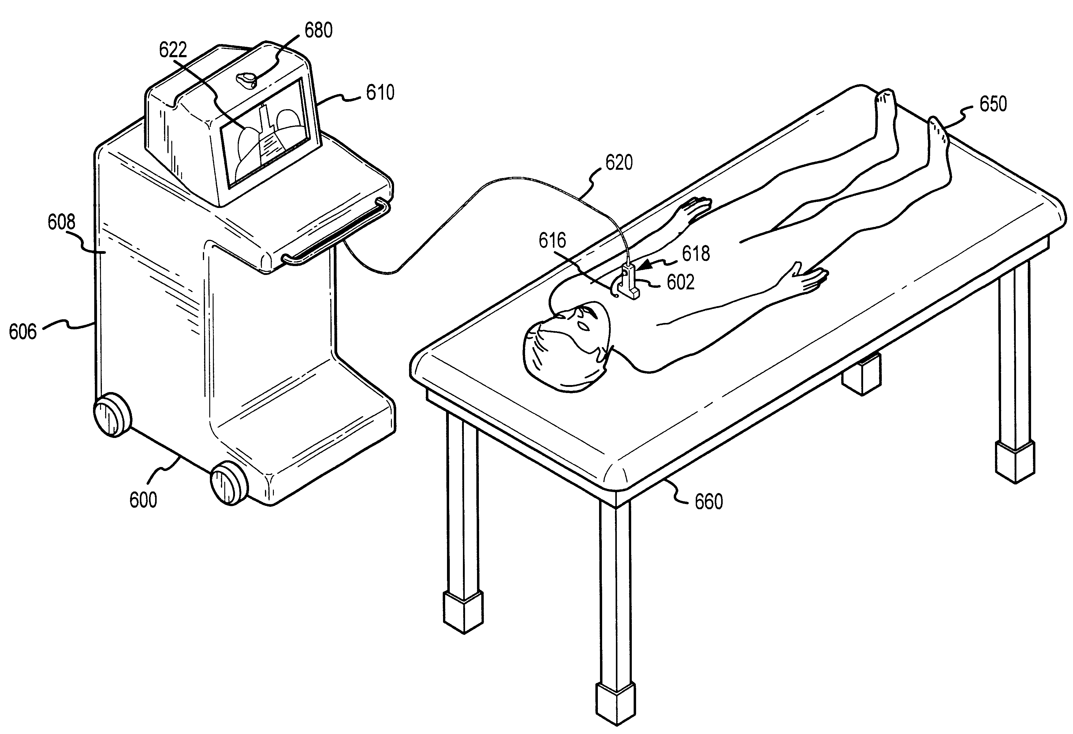
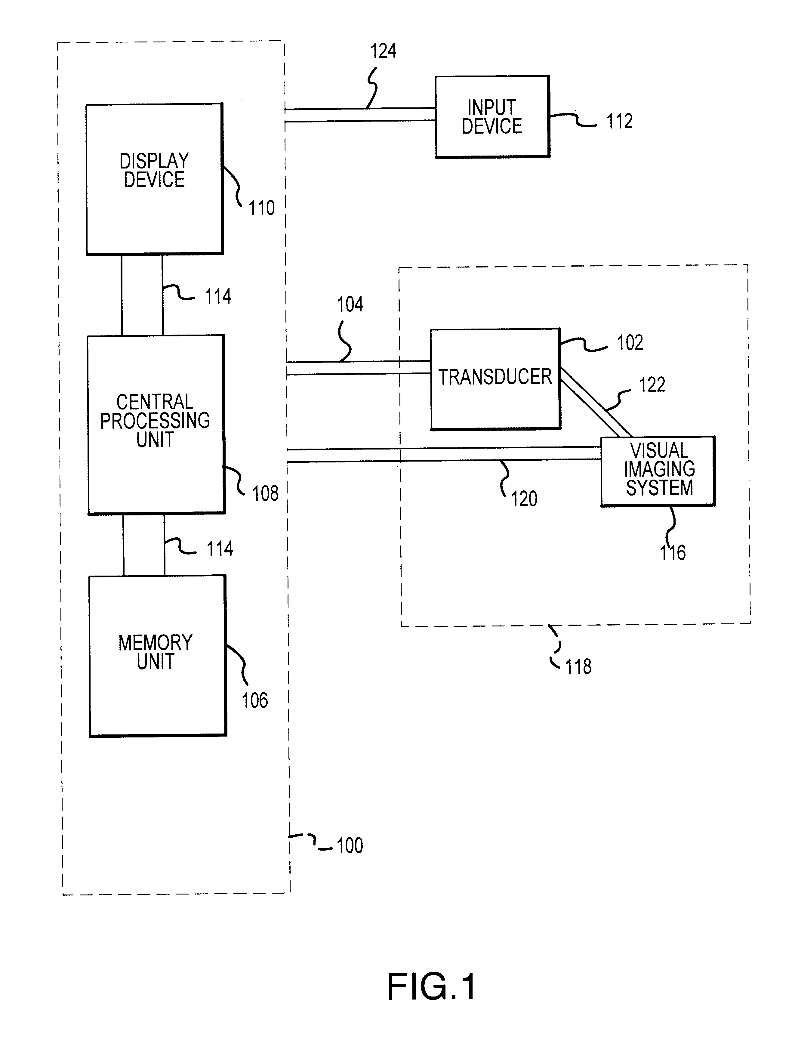
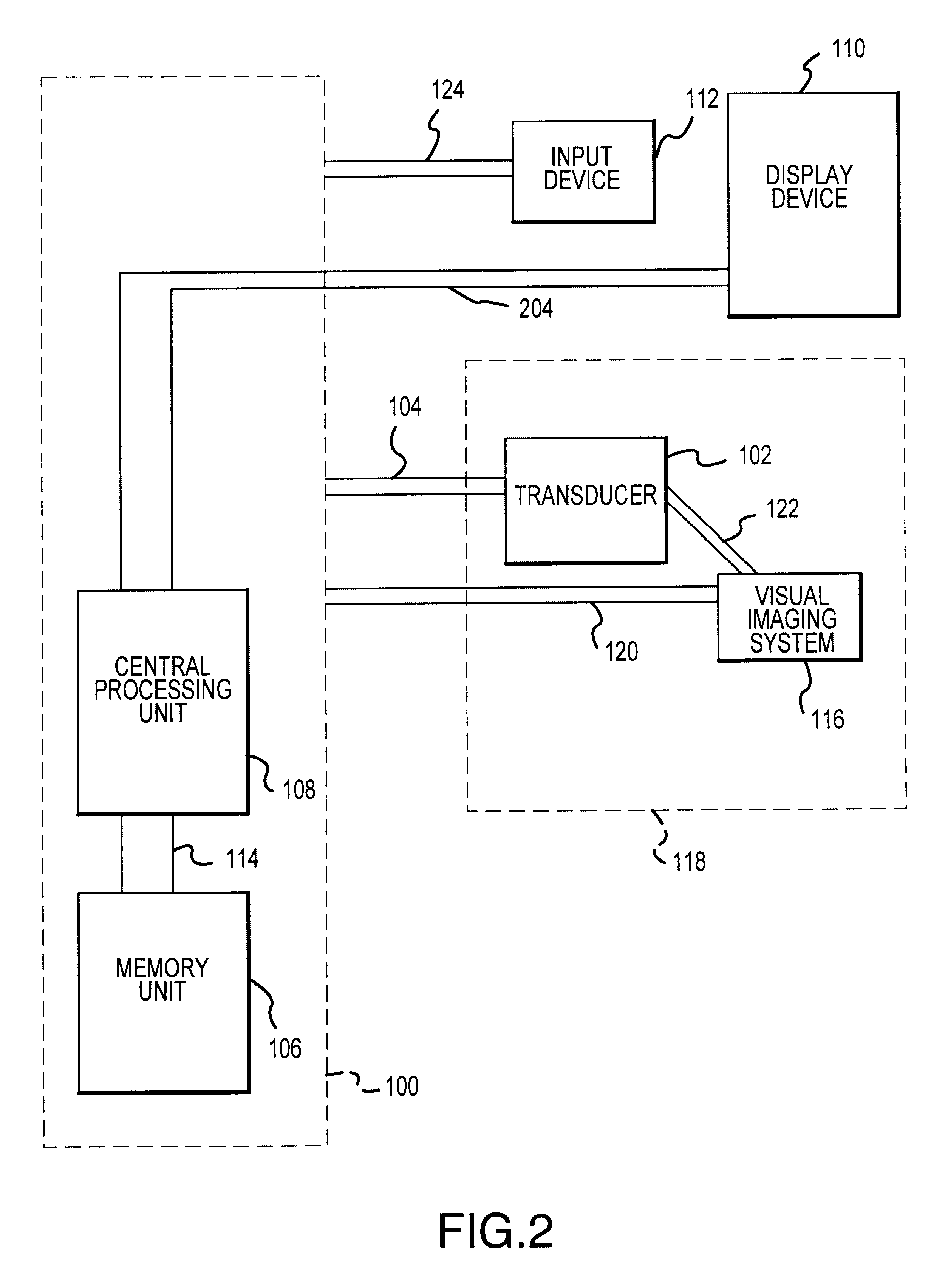
The present invention may be described herein in terms of various components and processing steps. It should be appreciated that such components and steps may be realized by any number of hardware components configured to perform the specified functions. For example, the present invention may employ various medical treatment devices, visual imaging and display devices, input terminals and the like, which may carry out a variety of functions under the control of one or more control systems or other control devices. In addition, those skilled in the art will appreciate that the present invention may be practiced in any number of medical contexts and that the exemplary embodiment relating to an ultrasonic transducer as described herein is merely one exemplary application for the invention. For example, the principles, features and methods discussed may be applied to any medical application. Further, various aspects of the present invention may be suitably applied to other industrial, m...


PUM


Abstract

A non-invasive visual imaging system is provided, wherein the imaging system procures an image of a transducer position during diagnostic or therapeutic treatment. In addition, the system suitably provides for the transducer to capture patient information, such as acoustic, temperature, or ultrasonic images. For example, an ultrasonic image captured by the transducer can be correlated, fused or otherwise combined with the corresponding positional transducer image, such that the corresponding images represent not only the location of the transducer with respect to the patient, but also the ultrasonic image of the region of interest being scanned. Further, a system is provided wherein the information relating to the transducer position on a single patient may be used to capture similar imaging planes on the same patient, or with subsequent patients. Moreover, the imaging information can be effectively utilized as a training tool for medical practitioners.

Description

1. Field of the InventionThis invention generally relates to a non-invasive ultrasonic system, and more particularly, to a system which is capable of generating ultrasonic imaging data and information related to the positioning of a transducer during medical treatment and diagnosis.2. Description of the Related ArtThere are a number of well known non-invasive imaging techniques for the diagnosis and treatment of patients. These techniques generally allow a physician to obtain high fidelity views of the human anatomic structure without the advent of invasive procedures. Such imaging systems which provide a cross-sectional (tomographic) view of the human body include computer-aided tomography (CAT scans) x-ray imagers magnetic resonance (MRI) imagers, positron emission tomographic scanning (PET), and magnetoencephotographic scanning (MEG). Typically, when a patient is scanned using one of these conventional cross-sectional imaging techniques, the patient's entire body or limb is image...

Claims


Application Information

Patent Timeline
Patent Type & Authority Patents(United States)
IPC IPC(8): A61B8/00
CPCA61B8/00A61B8/463A61B8/42
Inventor SLAYTON, MICHAEL H.BARTHE, PETER G.
Owner GUIDED THERAPY SYSTEMS LLC
Why Eureka
Try Eureka