Rotational vibration testing apparatus

a technology of rotating vibration and testing apparatus, which is applied in vibration testing, mechanical vibration separation, instruments, etc., can solve the problems of affecting positioning accuracy, limiting the measuring frequency band, and enlarged the size of the apparatus

Inactive Publication Date: 2003-04-08
FUJITSU LTD
View PDF3 Cites 20 Cited by
  • Summary
  • Abstract
  • Description
  • Claims
  • Application Information

AI Technical Summary

Problems solved by technology

The rotational disturbances increasingly affect the positioning accuracy in an adverse manner.
Since the conventional rotational vibration testing apparatus is constructed to convert the rectilinear reciprocating vibration generated by the rectilinear vibration generator into a rotational reciprocating vibration by means of the link mechanism, as described above, there arises a problem in that the measuring frequency band is limited due to the resonance of the link mechanism.
Moreover, a combination of the rectilinear vibration generator and the link mechanism results in another problem in that the size of the apparatus is enlarged, substantially reducing transportability thereof.

Method used


Image

  • Rotational vibration testing apparatus
  • Rotational vibration testing apparatus
  • Rotational vibration testing apparatus

Examples


second embodiment

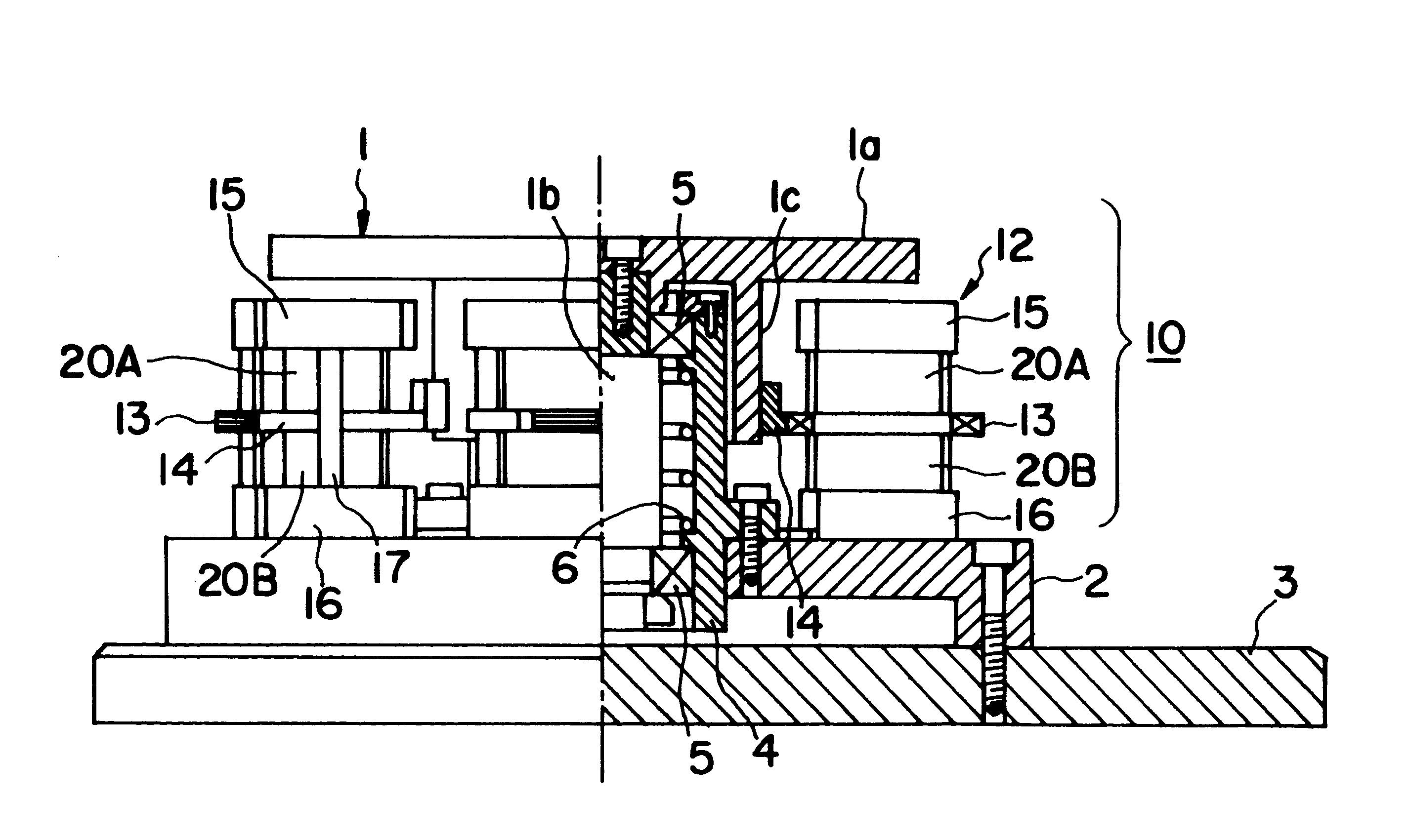
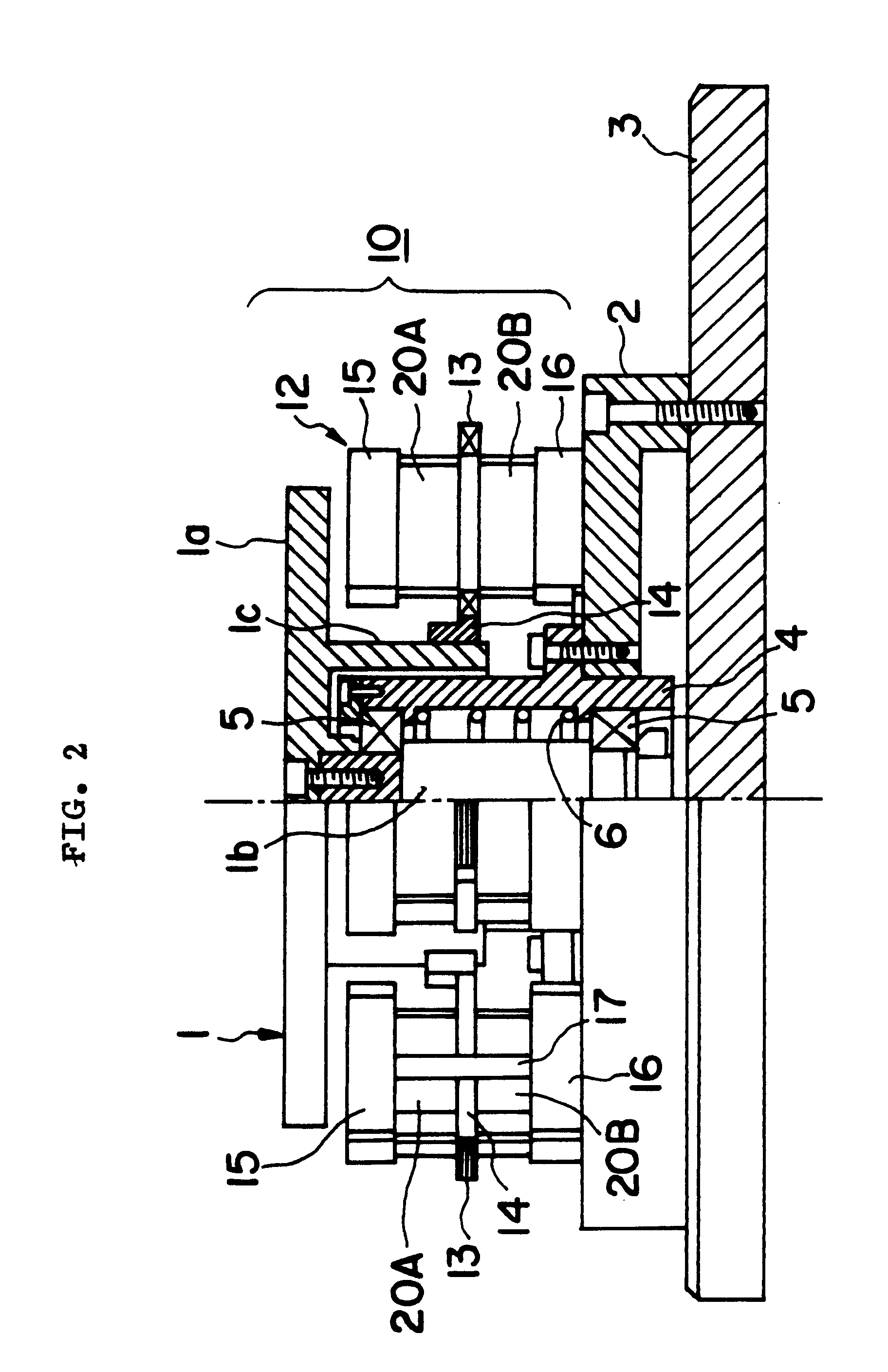
FIG. 6 is a cross sectional view showing a rotational vibration testing apparatus in accordance with the invention.

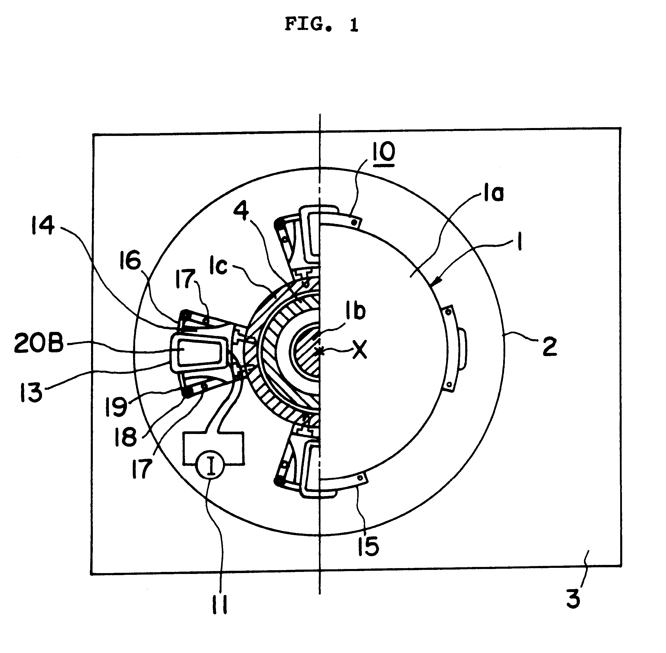
In FIG. 6, a vibration applying mechanism in the form of a VCM 10A comprises a magnetic circuit 12A, and coils 13 attached to coil frames 14 through a fastening element such as an adhesive or the like. The four coils 14 each mounting a coil 13 thereon are fixedly secured to a flange 1c at an equal circumferential pitch or interval about the axis of rotation X thereof.

first embodiment

The magnetic circuit 12A includes a yoke structure comprising an upper yoke 15, a lower yoke 16, an intermediate yoke 22 and side yokes (not shown) connected with ends of the upper, lower and intermediate yokes 15, 16 and 17 so as to form a substantially trapezoidal configuration, and a pair of permanent magnets 21A, 21B secured through an adhesive or the like to the upper and lower surfaces of the upper yoke 15. The permanent magnet 21A is formed into a curved plate as in the case of the permanent magnet 20A of the aforementioned first embodiment, and has a lower surface magnetized to an N pole. Similarly, the permanent magnet 21B is shaped into the same configuration as the permanent magnet 21A and has an upper surface magnetized to an N pole. Between the upper permanent magnet 21A and the intermediate yoke 22 and between the lower permanent magnet 21B and the intermediate yoke 22, respectively, there are formed predetermined spaces or magnetic gaps into which the effective or val...

embodiment 3

Although in the aforementioned second embodiment, the coils 13 are mounted on the flange 1c provided on the mounting plate 1a, this third embodiment is constructed such that coils 13 are mounted on a shaft 1b.


PUM


Abstract

A small-sized rotational vibration testing apparatus having a wide band of measuring frequencies and capable of directly driving a rotary table (1) to oscillate or vibrate in a rotational direction under the action of torque generated by a vibration applying mechanism. The rotary table (1) is rotatably mounted on a base (2), and a plurality of coil frames (14) each having a coil (13) attached thereto are mounted on a flange (1c) of the rotary table (1) at an equal circumferential pitch or interval about its axis of rotation. A plurality of magnetic circuits (12) are fixedly secured to the base (2) in such a manner that the center of each coil (13) is positioned at the center of an associated magnetic circuit (12).

Description

1. Field of the InventionThe present invention relates to a rotational vibration testing apparatus which is applicable to assessing the rotational vibration of a rotating object such as, for example, a magnetic disk and the like.2. Description of the Related ArtIn recent years, with magnetic disk drives, the density of tracks per inch is increasing, and the speed in seeking is becoming faster and faster, as a result of which it becomes important to enhance the accuracy of positioning a magnetic head. On the other hand, a rotary actuator is used as a rotating drive source for such magnetic disk drives, and such an actuator has a weak structure against rotational external disturbances, i.e., vibrations or oscillations in a direction in which a magnetic disk is driven to rotate. The rotational disturbances increasingly affect the positioning accuracy in an adverse manner.In these circumstances, in the development of magnetic disk drives, it is essential to perform assessment against ro...

Claims


Application Information

Patent Timeline
Patent Type & Authority Patents(United States)
IPC IPC(8): G01M7/00G01M7/04B06B1/04
CPCG01M7/045
Inventor JINZENJI, AKIHIDEARUGA, KEIJI
Owner FUJITSU LTD
Why Eureka
Try Eureka