
Communication apparatus and methods

a multi-port bridge and router technology, applied in the field of packet oriented multi-port bridges and routers, can solve the problems of complex topology, affecting performance, security or other aspects of network operations, and complex behavior of multi-bridge or multi-router networks, so as to improve the performance of forwarding computation

Inactive Publication Date: 2003-04-08
TELEFON AB LM ERICSSON (PUBL)
View PDF17 Cites 69 Cited by
  • Summary
  • Abstract
  • Description
  • Claims
  • Application Information

AI Technical Summary

Benefits of technology

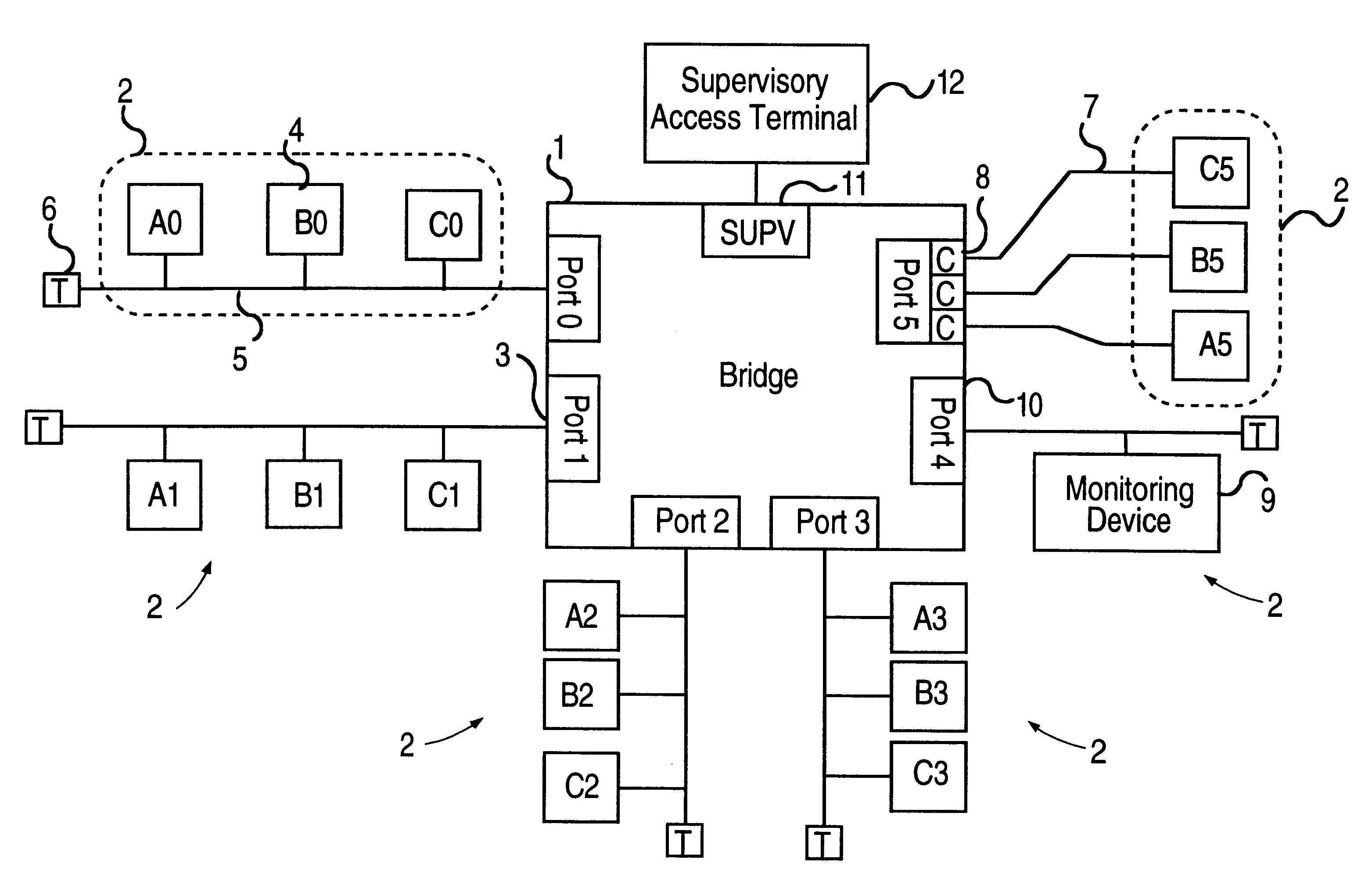
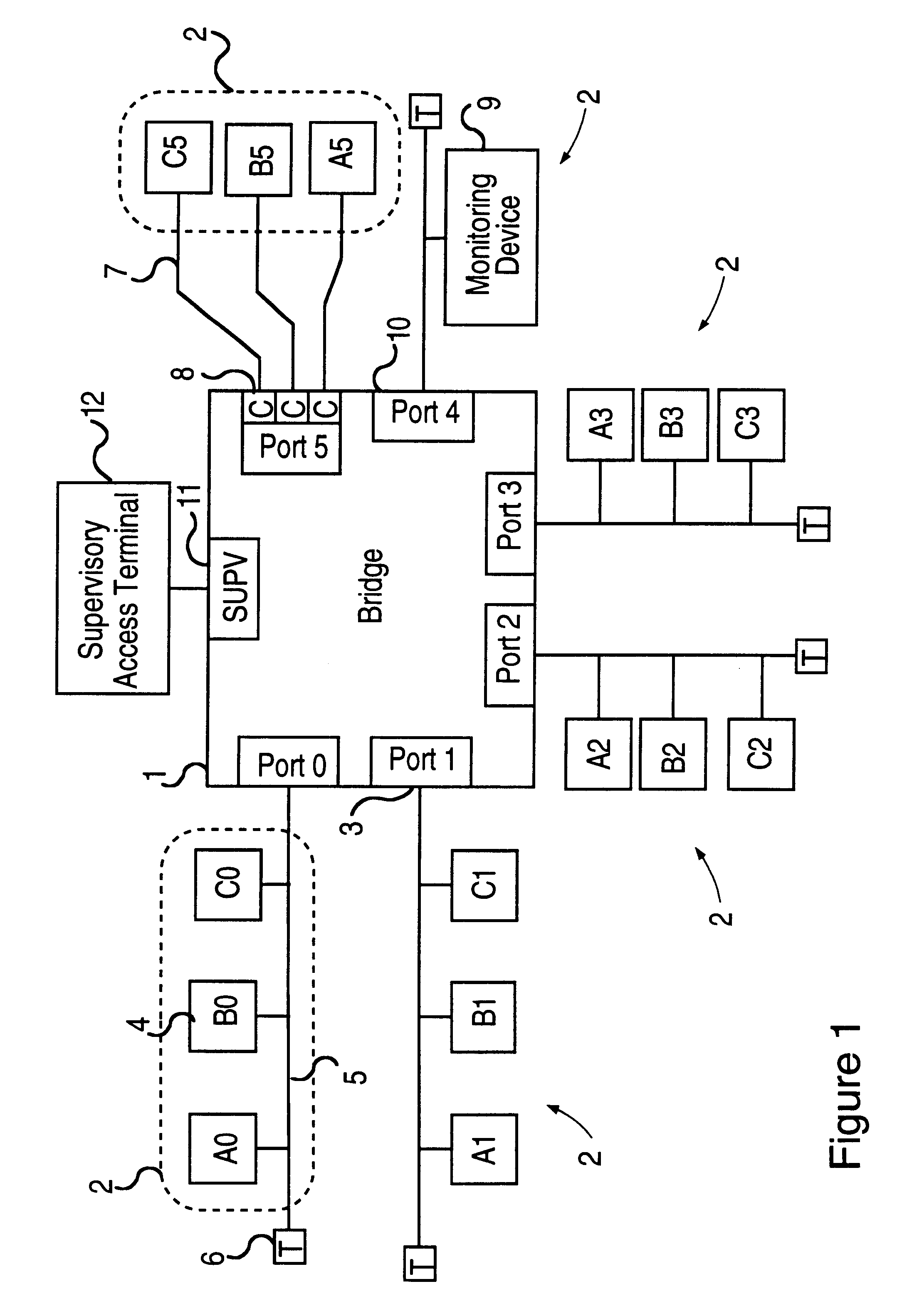
Forwarding of a packet from a monitored port to a monitoring port does not require the packet to be copied from one place to another in the bridge's internal buffer memory. Instead, an indirect scheme is specified, that allows a packet to be sent to one or more destination ports without moving the packet. Internal data structures are defined to support efficient packet forwarding and to define the ports to which a packet should be forwarded under various circumstances. The data structures are intended to promote efficient forwarding and also to support simple and regular modification when a port monitoring command is issued from the supervisory access terminal.
Another object of the invention is to "transmit" a single packet to multiple ports in an efficient manner and without the need to make multiple copies of the packet itself.
It is also an object of the invention to improve the performance of the forwarding computation by caching recent forwarding results in anticipation that they will be used in the near future.

Problems solved by technology

Larger networks can be built by using multiple bridges, routers, or combinations thereof, and the extent and topology of a multi-bridge or multi-router network can be quite complex.
Even small single-bridge networks can exhibit complex behavior which may affect performance, security or other aspects of network operations.
selves. Because of the need to capture and analyze large amounts of data, and the potential complexity of filtering, network monitors are expensive relative to other network components such as stations or b
A serious limitation of prior-art network monitors is that the monitor must be connected physically to the network segment to be monitored.
A further limitation is that the network monitor is not able to easily differentiate packets originating on the attached network segment and those originating on other network segments attached to the bridge and forwarded to the monitored network segment, especially if the packets have wrong addresses due to malfunction or sabotage.
A router, moreover, replaces the source address of the packet by the router address, which makes it even more difficult for the network monitor to determine where the packet originated.
In particular, it may be difficult or impossible for the monitor to isolate, for example, all the packets originating on a selected network segment.
The clear disadvantage of this approach is the cost of multiple Sniffers.
In particular, a Sniffer detecting a packet may be unable to determine the network segment on which the packet originated even if that network segment is connected to another Sniffer which has detected the packet, because the two Sniffers may be unable to determine whether the packet they have detected is the same packet or two different packets.
Additionally, each Distributed Sniffer must use some portion of the bandwidth of the monitored network to send information to the monitoring station, and thus the performance of the monitored network is affected.

Method used


Image

  • Communication apparatus and methods
  • Communication apparatus and methods
  • Communication apparatus and methods

Examples


Embodiment Construction

The purpose of the bridge to be described below is to connect together multiple packet-based segments of a network, allowing efficient communications between stations on each network segment and also between stations located on different network segments connected to the bridge. It is also possible for stations on network segments not connected to a common bridge to communicate, provided that there is at least one segment-to-segment path between the stations.

The example provided here is of a bridge, however, the operation is similar for routers, and the extension to routers will be clear to those skilled in the art.

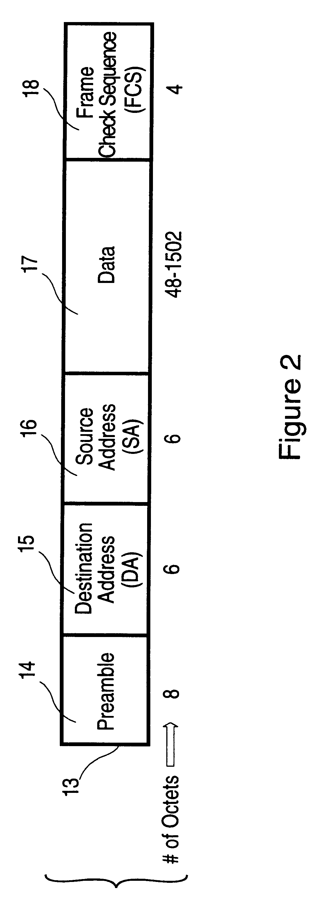
In some embodiments, network segments attached to the bridge will employ a packet-based communication protocol based on either Ethernet or FDDI. Other packet-based protocols are possible. The details of Ethernet and FDDI protocols are well known and are documented in standards, particularly in IEEE Standard 802.3 for Ethernet and ANSI Standard X3T9.5 for FDDI. The followi...


PUM


Abstract

A multi-port packet-based bridge is described in which packet transmissions on particular ports or between ports may be monitored on another, monitoring port. Efficient operation is realized by using a multi-processor environment and data structures that allow a packet received on one port to be transmitted to multiple ports without being "copied" multiple times. By using a Supervisory Access Terminal, it is possible to specify various circumstances under which a packet will be sent to the monitoring port. These circumstances include monitoring of all packets incoming to a selected port (or ports), all packets forwarded to a selected port (or ports), and packets generated internally and sent to a selected port (or ports). In addition, all packets forwarded from one selected port to another selected port may be monitored. Port monitoring is supported by particular data structures that promote efficient dispatching of packets and by a Bridging Cache that retains the results of recent dispatch calculations. Similar techniques are applied to multi-port routers.

Description

FIELD OF INVENTIONThis invention relates to packet oriented multi-port bridges and routers and, in particular, to the monitoring of packet traffic arriving at the bridges and routers or generated internally.DESCRIPTION OF RELATED ARTMulti-port bridges and routers allow the connection of two or more packet-based networks of possibly different types. Information in such networks is transmitted by means of packets, each containing data and appropriate addressing information. The purpose of the bridge or router is to relay packets between network segments (a process called forwarding) so that stations connected to different network segments may communicate. An example of a packet-based network protocol is that implemented by the IEEE 802.3 Ethernet standard.Larger networks can be built by using multiple bridges, routers, or combinations thereof, and the extent and topology of a multi-bridge or multi-router network can be quite complex. Even small single-bridge networks can exhibit compl...

Claims


Application Information

Patent Timeline
Patent Type & Authority Patents(United States)
IPC IPC(8): H04L12/46H04L12/26
CPCH04L12/2602H04L43/00H04L12/46
Inventor MURTHY, MANOHARWAKERLY, JOHN F.LAURSEN, ARTHUR I.
Owner TELEFON AB LM ERICSSON (PUBL)
Learn More